| Protective Relays | |
|---|---|

|
NEC Requirements and UL StandardsThe National Electric Code 225.56 Inspections and Tests.
The complete electrical system design, including settings for protective, switching, and control circuits, shall be prepared in advance and made available on request to the authority having jurisdiction and shall be performance tested when first installed on-site. Each protective, switching, and control circuit shall be adjusted in accordance with the system design and tested by actual operation using current injection or equivalent methods as necessary to ensure that each and every such circuit operates correctly to the satisfaction of the authority having jurisdiction. Each protective relay shall be demonstrated to operate by injecting current or voltage, or both, at the associated instrument transformer output terminal and observing that the associated switching and signaling functions occur correctly and in proper time and sequence to accomplish the protective function intended. |

|
|
| NETA Test Procedure | |
|---|---|
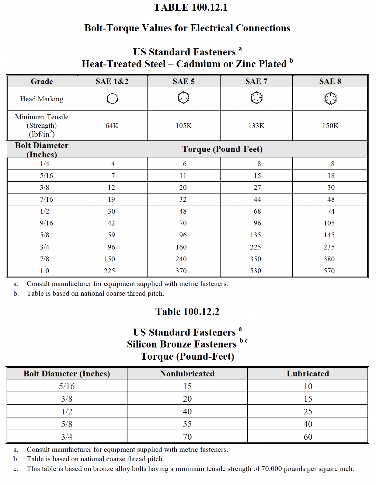
NETA ATS7.9.1 Protective Relays, Electromechanical and Solid-StateA. Visual and Mechanical Inspection:
B. Electrical Tests:
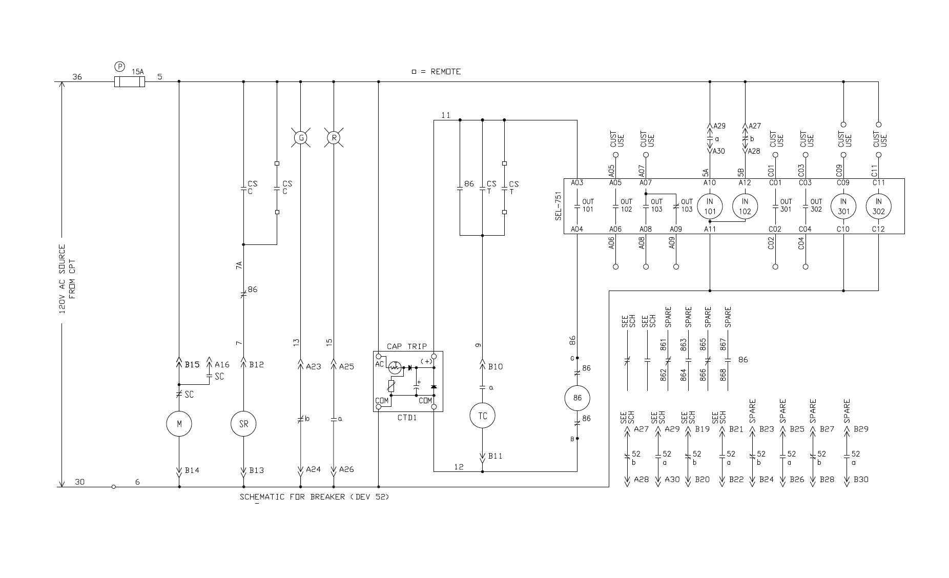
Verify that each of the relay contacts performs its intended function in the control scheme including breaker trip tests, close inhibit tests, 86 lockout tests, and alarm functions. Refer to Section 8. C. Test Values – Visual and Mechanical
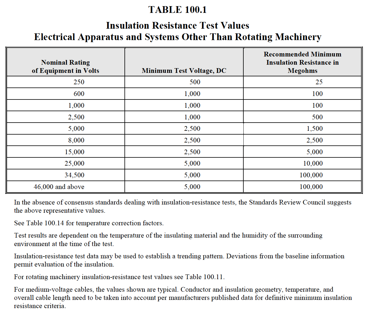
D. Test Values – Electrical
NETA MTS7.9.2 Protective Relays, Microprocessor-BasedA. Visual and Mechanical Inspection:
B. Electrical Tests
Check functional operation of each element used in the protection scheme as described for electromechanical and solid-state relays in 7.9.1.B.3. When not otherwise specified, use manufacturer’s recommended tolerances. C. Test Values – Visual and Mechanical
D. Test Values – Electrical
NETA ATS
/ MTS

NETA ATS
/ MTS


|
|
| Protection Functions | |
|---|---|

|
|
Basics:
Buff Boof IEEE
|
|


