SIDEBAR SKINS

HEADER SKINS

Total Collections
Conductors
Low Voltage, less than 600V

The National Electric Code 310.3 Conductors

  1. Article 310.3(A) Minimum Size of Conductors.
  2. The minimum size of conductors for voltage ratings up to and including 2000 volts shall be 14 AWG copper or 12 AWG aluminum or copper-clad aluminum, except as permitted elsewhere in this Code.

  3. Article 225.56(B) Conductor Material.
  4. Conductors in this article shall be of aluminum, copper-clad aluminum, or copper unless otherwise specified.

    Solid aluminum conductors 8, 10, and 12 AWG shall be made of an AA-8000 series electrical grade aluminum alloy conductor material. Stranded aluminum conductors 8 AWG through 1000 kcmil marked as Type RHH, RHW, XHHW, THW, THHW, THWN, THHN, service-entrance Type SE Style U, and SE Style R shall be made of an AA-8000 series electrical grade aluminum alloy conductor material.

Key Terms
Insulation:

Every electric wire is carefully covered with some form of electrical insulation. The wire itself is usually copper or aluminum, which is known to be a good conductor of the electric current that powers your equipment. The insulation must be just the opposite from a conductor: it should resist current and keep the current in its path along the conductor

Charging
Current:

The measured Insulation resistance will be determined by the voltage applied and the resultant current (R = E/I). There are a number of things that affect current, including temperature of the insulation and humidity, as mentioned in the previous section. Right now, let’s just consider the nature of current through insulation and the effect of how long voltage is applied.

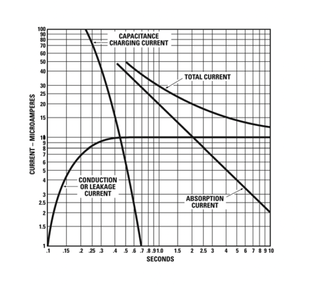
Current through and along insulation is made up partly of a relatively steady current in leakage paths over the insulation surface. Electricity also flows through the volume of the insulation. Actually, as shown in Fig. 5, our total current comprises three components:

  1. Capacitance Charging Current

    Current that starts out high and drops after the insulation has been charged to full voltage (much like water flow in a garden hose when you first turn on the spigot).

  2. Absorption Current

    Also an initially high current which then drops (for reasons discussed under the section Time-Resistance Method).

  3. Conduction or Leakage Current

    A small essentially steady current both through and over the insulation.

The total current is the sum of the three components and it is this current that can be measured directly by a microammeter, or in terms of megohms at a particular voltage by means of a Megger instrument (ohmmeter). Because the total current depends upon the time that the voltage is applied, you can see now why Ohm’s Law R = E/I only holds, theoretically, at an infinite time (that is, you’d have to wait forever before taking a reading).

Test
Temperature
  1. Effects of Temperature on Insulation Resistance
  2. The resistance of insulating materials decreases markedly with an increase in temperature.

  3. Comparing Test Values
  4. reliable comparisons between readings, you should correct the readings to a base temperature, such as 20℃, or take all your readings at approximately the same temperature

  5. Rule of Thumb
  6. For every 10℃ increase in temperature, halve the resistance; or, for every 10℃ decrease, double the resistance.

Dielectric
Absorption
Ratio
  1. Effects of Temperature on Insulation Resistance
  2. The resistance of insulating materials decreases markedly with an increase in temperature.

  3. Comparing Test Values
  4. The ratio of two time-resistance readings (such as a 60-second reading divided by a 30-second reading) is called a dielectric absorption ratio. It is useful in recording information about insulation. If the ratio is a 10-minute reading divided by a 1-minute reading, the value is called the polarization index.

NETA Test Procedure

NETA ATS

7.3.2 Cable Low-Voltage, 600-Volt Maximum

NOTE: This category consists of power transformers with windings rated 600 volts or less and sizes equal to or less than 167 kVA single-phase or 500 kVA three-phase.
A. Visual and Mechanical Inspection:
  1. Compare equipment nameplate data with drawings and specifications.
  2. Inspect physical and mechanical condition..
  3. Inspect anchorage, alignment, and grounding.
  4. Verify that resilient mounts are free and that any shipping brackets have been removed.
  5. Inspect bolted electrical connections for high resistance using one or more of the following methods:
    1. Use of a low-resistance ohmmeter in accordance with Section 7.2.1.1.B.1.
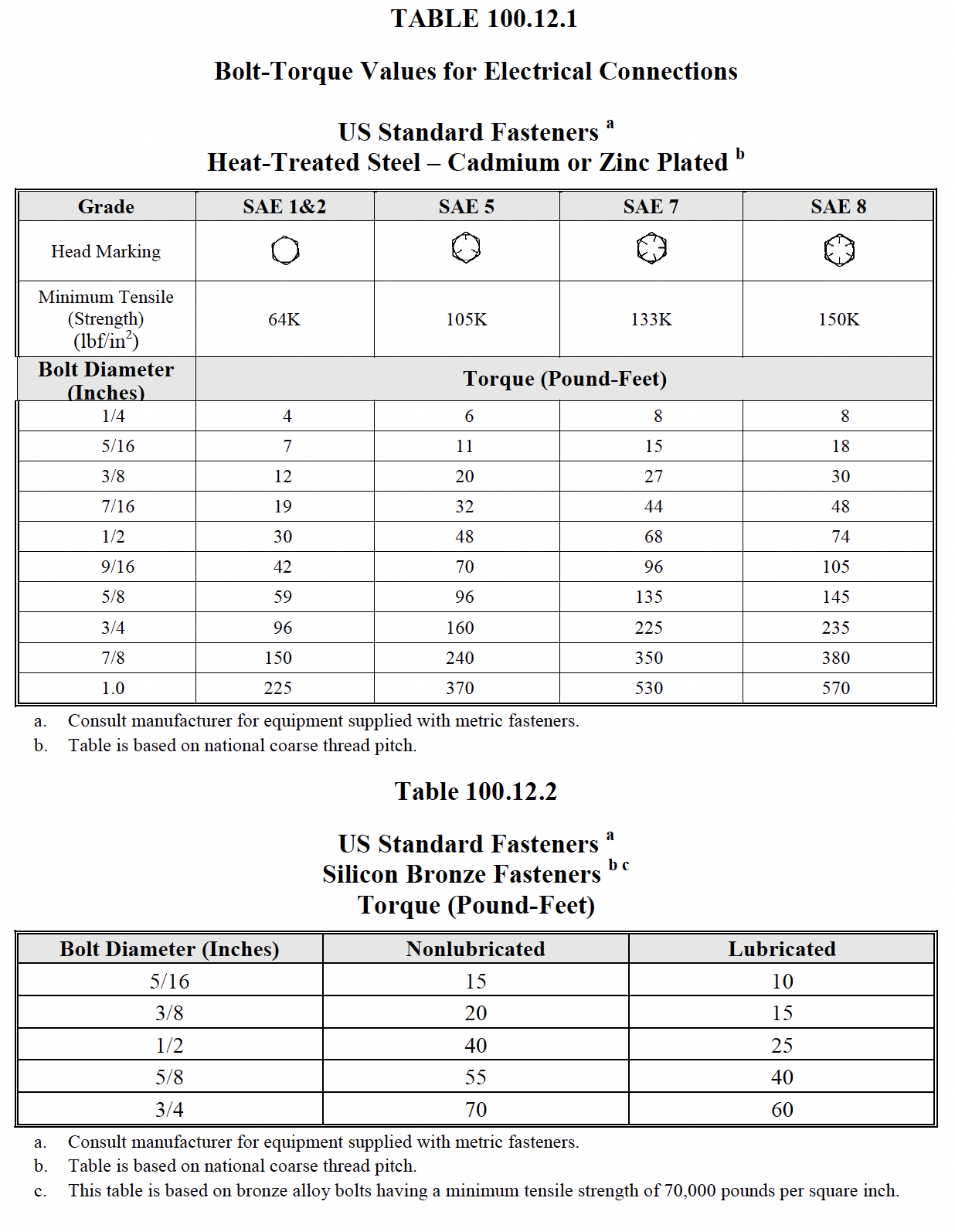
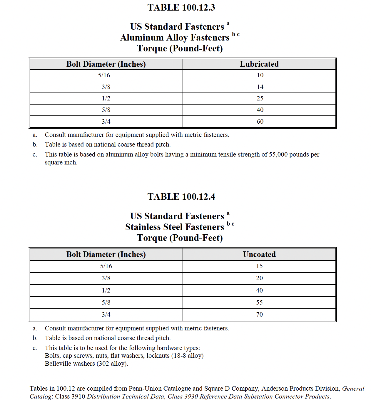
    2. Verify tightness of accessible bolted electrical connections by calibrated torque-wrench method in accordance with manufacturer’s published data or Table 100.12.
    3. Perform thermographic survey in accordance with Section 9.
  6. Verify that as-left tap connections are as specified.
B. Electrical Tests:
  1. Perform resistance measurements through bolted connections with a low-resistance ohmmeter, if applicable, in accordance with Section 7.2.1.1.A.6.1.
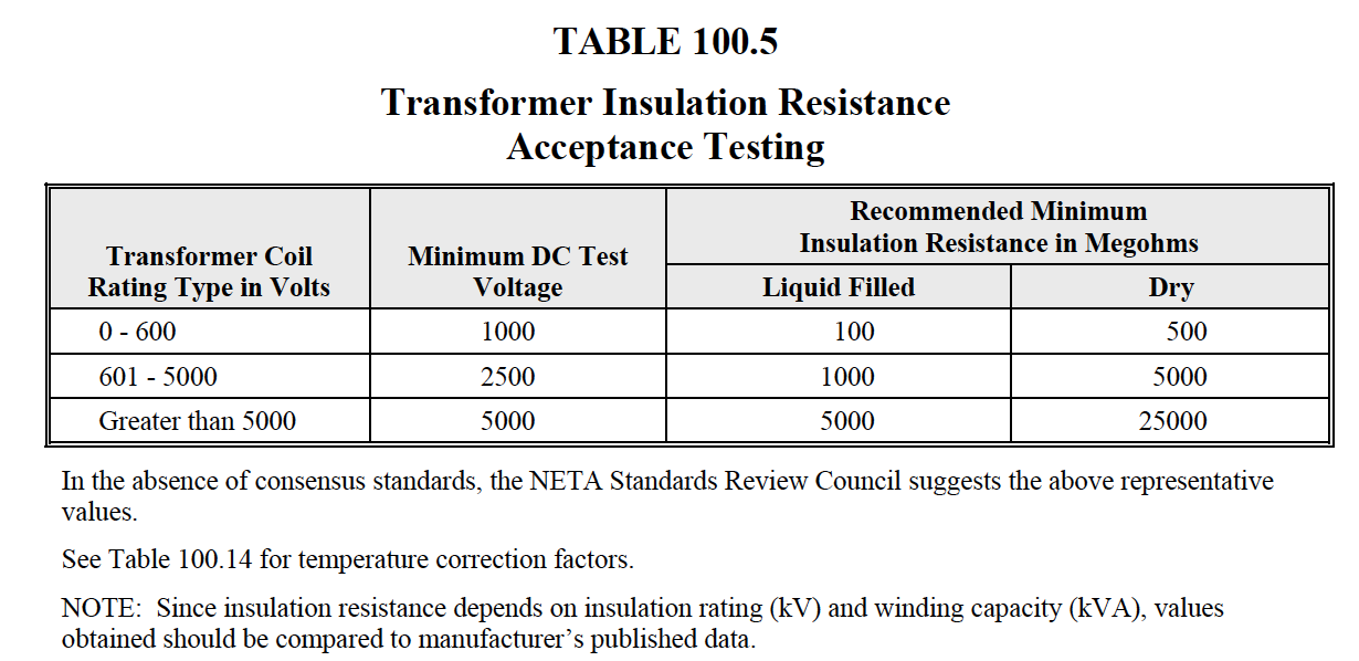
  2. Perform insulation-resistance tests winding-to-winding and each winding-to-ground. Apply voltage in accordance with manufacturer’s published data or in the absence of manufacturer’s published data, use Table 100.5. Calculate polarization index.
  3. *Perform turns-ratio tests at all tap positions.
  4. Verify correct secondary voltage phase-to-phase and phase-to-neutral after energization and prior to loading.
C. Test Values – Visual and Mechanical
  1. Compare bolted connection resistance values to values of similar connections. Investigate values which deviate from those of similar bolted connections by more than 50 percent of the lowest value. (7.2.1.1.A.6.1)
  2. Bolt-torque levels shall be in accordance with manufacturer’s published data. In the absence of manufacturer’s published data, use Table 100.12. (7.2.1.1.A.6.2)
  3. Results of the thermographic survey shall be in accordance with Section 9. (7.2.1.1.1.6.3)
  4. Tap connections are left as found unless otherwise specified. (7.2.1.1.A.7)
D. Test Values – Electrical
  1. Compare bolted electrical connection resistances to values of similar connections. Investigate values which deviate from those of similar bolted connections by more than 50 percent of the lowest value.
  2. Minimum insulation-resistance values of transformer insulation shall be in accordance with manufacturer’s published data. In the absence of manufacturer’s published data, use Table 100.5. Values of insulation resistance less than this table or manufacturer’s recommendations should be investigated. The polarization index shall not be less than 1.0.
  3. Turns-ratio test results shall not deviate by more than one-half percent from either the adjacent coils or the calculated ratio.
  4. Phase-to-phase and phase-to-neutral secondary voltages shall be in agreement with nameplate data.

NETA MTS

7.3.2 Cable Low-Voltage, 600-Volt Maximum

A. Visual and Mechanical Inspection:
  1. Inspect exposed sections of cables for physical damage and evidence of overheating.
  2. Inspect bolted electrical connections for high resistance using one or more of the following methods:
    1. Use of a low-resistance ohmmeter in accordance with Section 7.3.2.B.1.
    2. Verify tightness of accessible bolted electrical connections by calibrated torque-wrench method in accordance with manufacturer’s published data or Table 100.12.
    3. Perform a thermographic survey in accordance with Section 9.Perform a thermographic survey in accordance with Section 9.Perform a thermographic survey in accordance with Section 9.
  3. Inspect compression-applied connectors for correct cable match and indentation.
B. Electrical Tests:
  1. Perform resistance measurements through bolted connections with a low-resistance ohmmeter in accordance with Section 7.3.2.A.2.1.
  2. Perform an insulation-resistance test on each conductor with respect to ground and adjacent conductors. The applied potential shall be 500 volts dc for 300-volt rated cable and 1000 volts dc for 600-volt rated cable. The test duration shall be one minute.
  3. Verify uniform resistance of parallel conductors.
C. Test Values – Visual and Mechanical
  1. Compare bolted connection resistance values to values of similar connections. Investigate values which deviate from those of similar bolted connections by more than 50 percent of the lowest value. (7.3.2.A.2.1)
  2. Bolt-torque levels should be in accordance with manufacturer’s published data. In the absence of manufacturer’s published data, use Table 100.12. (7.3.2.A.2.2)
  3. Results of the thermographic survey shall be in accordance with Section 9. (7.3.2.A.2.3)
D. Test Values – Electrical
  1. mpare bolted connection resistance values to values of similar connections. Investigate values which deviate from those of similar bolted connections by more than 50 percent of the lowest value.
  2. Insulation-resistance values should be comparable to previously obtained results and similar circuits but not less than two megohms.
  3. Deviations in resistance between parallel conductors shall be investigated.
NETA ATS / MTS
TABLE 100.5
Neta Table 100.5
NETA ATS / MTS
TABLE 100.12
Neta Table 100.5 Neta Table 100.5