| Medium Voltage Cables | |
|---|---|
| Operating Voltage greater than 600V | |
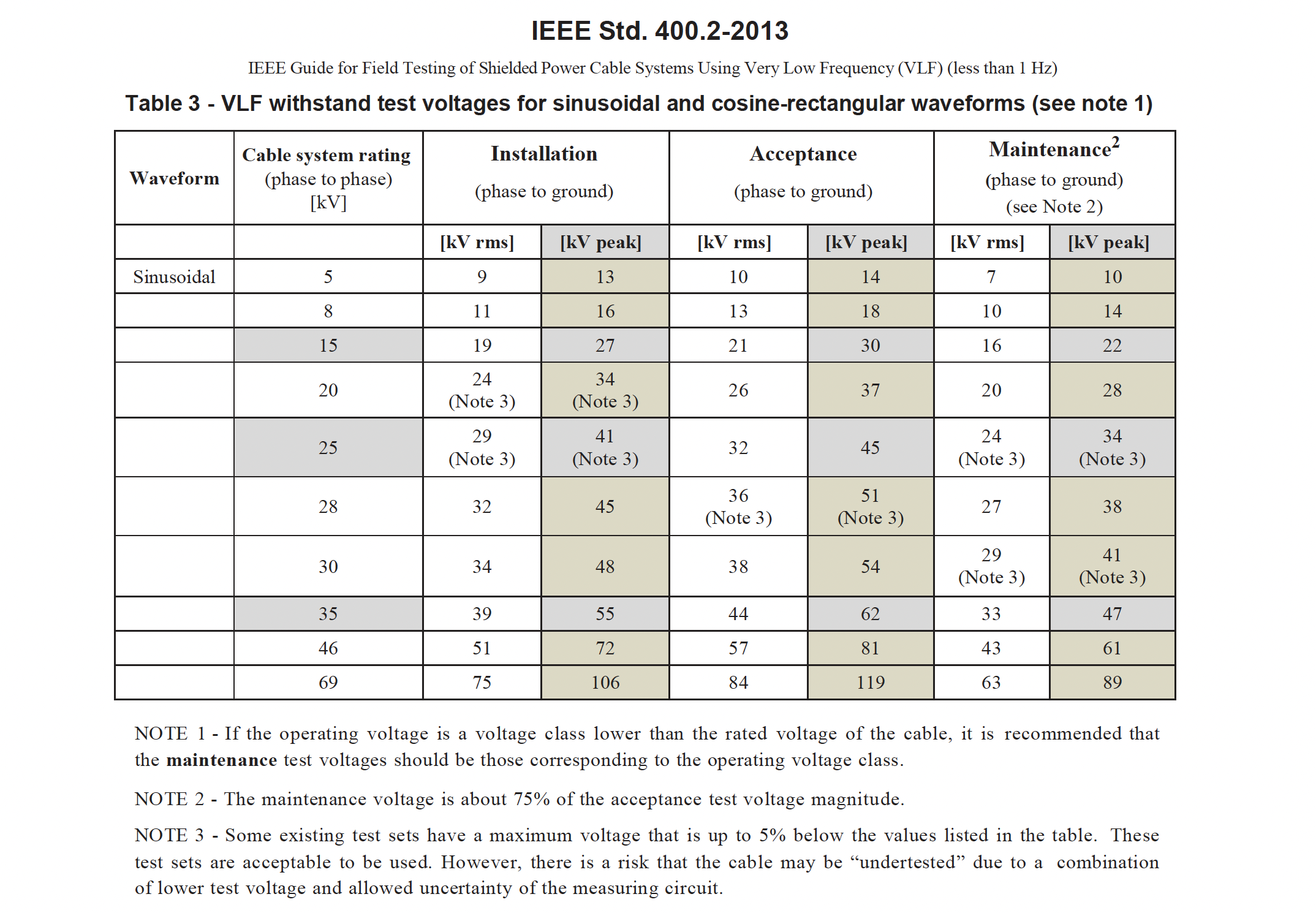
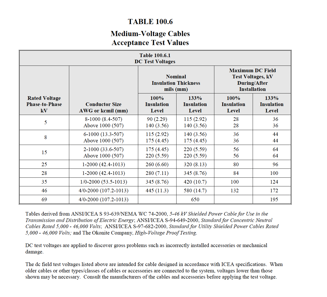
High Potential Testing
|
|
| NETA Test Procedure | |
|---|---|
NETA ATS7.3.3 Cables, Medium- and High-VoltageA. Visual and Mechanical Inspection:
B. Electrical Tests:
C. Test Values – Visual and Mechanical
D. Test Values – Electrical
NETA MTS7.3.3 Shielded Cables, Medium- and High-VoltageA. Visual and Mechanical Inspection:
B. Electrical Tests:
C. Test Values – Visual and Mechanical
D. Test Values – Electrical
NETA ATS
/ MTS
TABLE
100.5
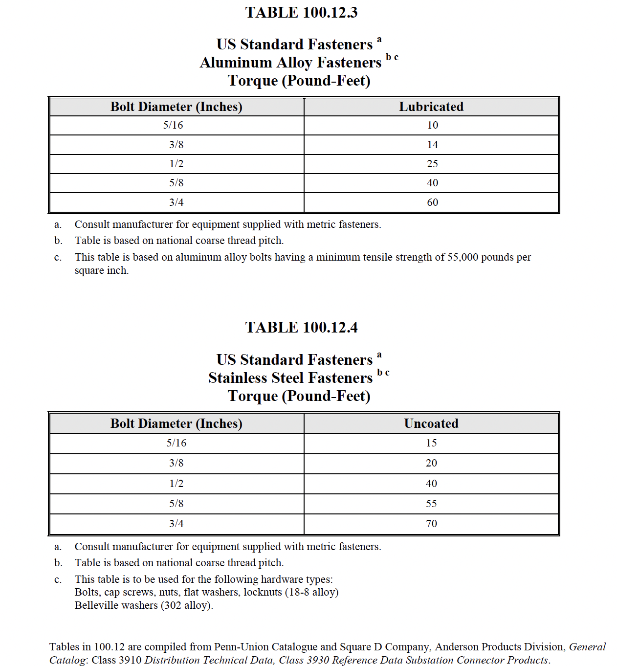
NETA ATS
/ MTS
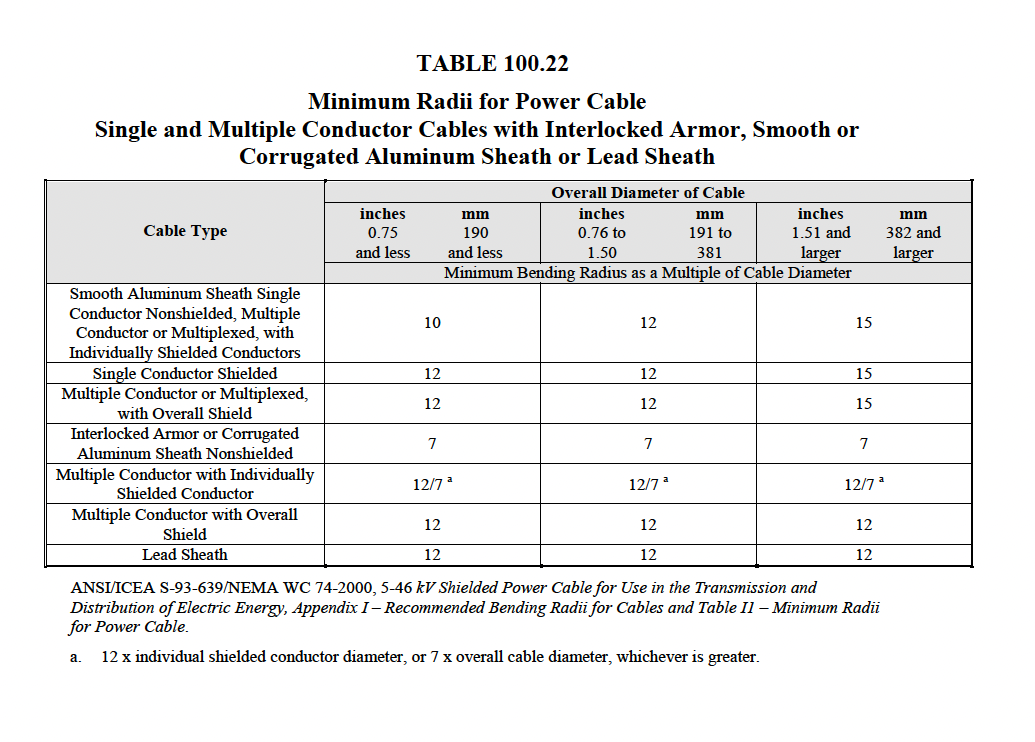
|
|
| Insulation Resistance | |
|---|---|
| DESCRIPTION: |
This test is performed at or above rated voltage to determine if there are low resistance paths to ground or between winding to winding as a result of winding insulation deterioration. The test measurement values are affected by variables such as temperature, humidity, test voltage, and size of transformer. This test should be conducted before and after repair or when maintenance is performed. The test data should be recorded for future comparative purposes. The test values should be normalized to 20°C for comparison purposes |
| PURPOSE: |
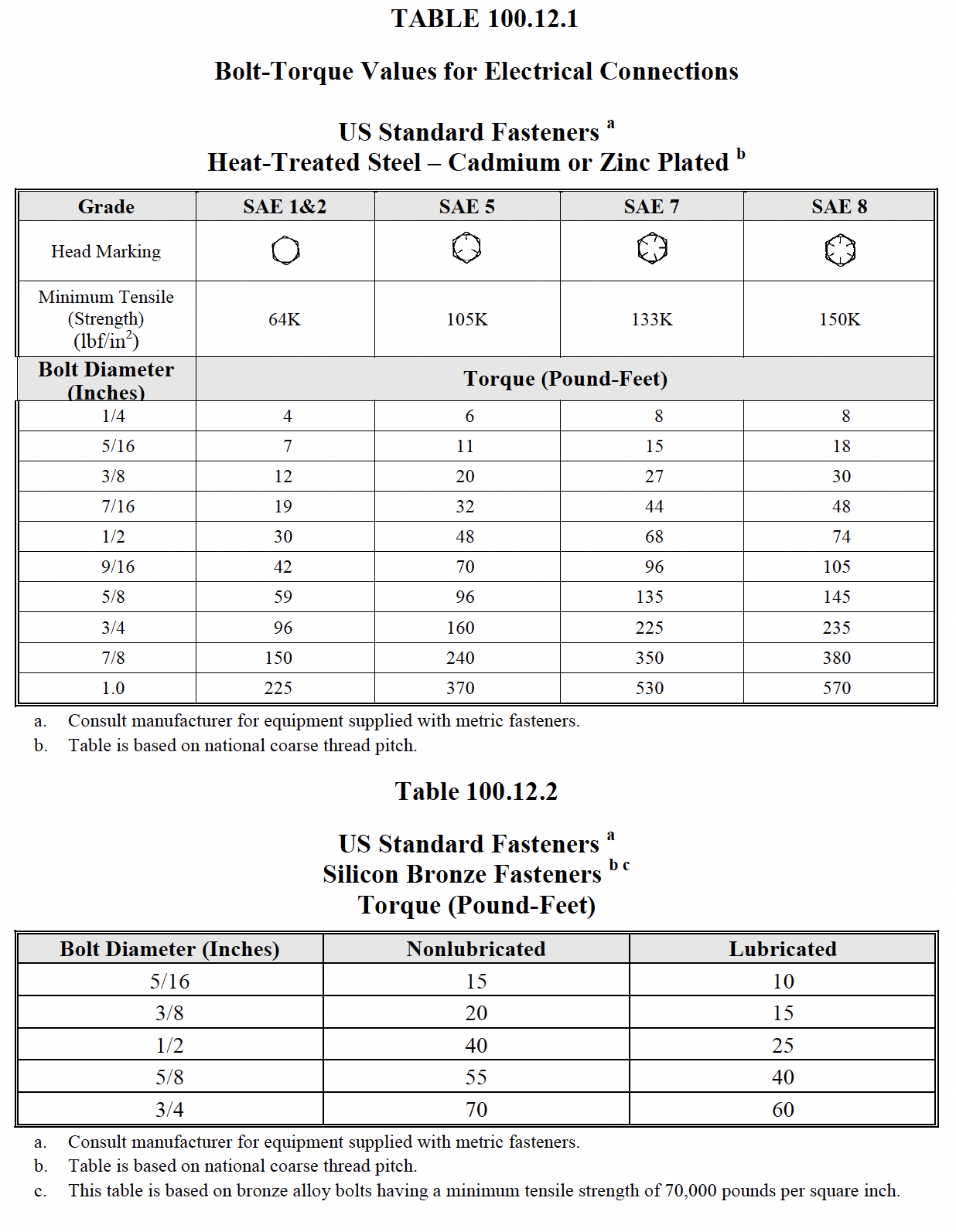
The IR test is of value for future comparative purposes and also for determining the suitability of the transformer of energizing or application of the high-potential (hi-pot) test. Insulation-resistance tests should be performed on winding-to-winding and each winding-to-ground. Apply voltage in accordance with manufacturer’s published data. In the absence of manufacturer’s published data, use Table 100.5. Calculate polarization index |
| PROCEDURE: |
Test Connections
Test Duration : 1 minute
Megohmmeter reading should be maintained for a period of 1 min. |
| TEST RESULTS: |
Insulation Resistance test:Acceptable test values are shown below on NETA Table 100.5
Polarization Index (PI) test:Test Duration : 10 minuteThis is an extension of the IR test. In this test, the two IR measurements are taken, the fi rst reading at 1 min and the second reading at 10 min. Then the ratio of the 10 min reading to 1 min reading is calculated to give the PI dielectric absorption value. A PI of winding-to-winding and winding-to-ground should be determined. A PI below 2 is indicative of insulation deterioration and cause for further investigation.NETA ATS TABLE
100.5
Electrical Apparatus and Systems Other Than Rotating Machinery 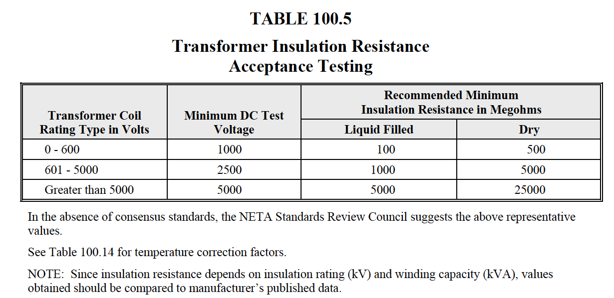
NETA MTS TABLE
100.5
Electrical Apparatus and Systems Other Than Rotating Machinery 
NETA ATS TABLE
100.14
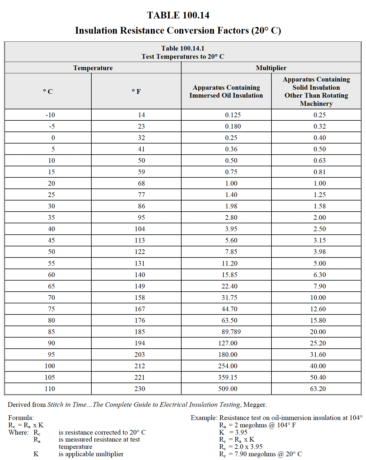
|
| Dieletric Withstand Test Methods | ||||||||||||||||||||
|---|---|---|---|---|---|---|---|---|---|---|---|---|---|---|---|---|---|---|---|---|

|
||||||||||||||||||||
What Is Tan δ, Or Tan Delta?Tan Delta, also called Loss Angle or Dissipation Factor testing, is a diagnostic method of testing cables to determine the quality of the cable insulation. This is done to try to predict the remaining life expectancy and in order to prioritize cable replacement and/or injection. It is also useful for determining what other tests may be worthwhile. What Is Tan δ, Or Tan Delta?If the insulation of a cable is free from defects, like water trees, electrical trees, moisture and air pockets, etc., the cable approaches the properties of a perfect capacitor. It is very similar to a parallel plate capacitor with the conductor and the neutral being the two plates separated by the insulation material. In a perfect capacitor, the voltage and current are phase shifted 90 degrees and the current through the insulation is capacitive. If there are impurities in the insulation, like those mentioned above, the resistance of the insulation decreases, resulting in an increase in resistive current through the insulation. It is no longer a perfect capacitor. The current and voltage will no longer be shifted 90 degrees. It will be something less than 90 degrees. The extent to which the phase shift is less than 90 degrees is indicative of the level of insulation contamination, hence quality/reliability. This “Loss Angle” is measured and analyzed. Below is a representation of a cable. The tangent of the angle δ is measured. This will indicate the level of resistance in the insulation. By measuring IR/IC (opposite over adjacent – the tangent), we can determine the quality of the cable insulation. In a perfect cable, the angle would be nearly zero. An increasing angle indicates an increase in the resistive current through the insulation, meaning contamination. The greater the angle, the worse the cable. How Long A Cable Can I Test?That depends on the AC voltage source used. The standard VLF unit from High Voltage, Inc. can test 3-4 miles of cable: one model can test 30 miles. It is generally advantageous to test shorter lengths rather than a long cable, because the shorter the section of cable that is tested, the more precise we can be in determining where the cable is good or bad. Can The Test Find The Locations Of Cable Defects?No. Tan delta tests the cable from point A to point B and gives an assessment of the insulation quality between those points. A determination can then be made if, and when, to replace or enhance the cable. For any value of tan delta, there could be many minor defects or a few major defects: it cannot discriminate. When you are tan delta testing, you are only determining how good a cable is between two points. Again, it’s not a faultfinding tool. It is a tool to permit a utility to make educated decisions regarding cable replacement This assumes the cable being tested is in conduit and entire lengths will be replaced. In direct buried situations, a better test is to use the VLF unit as an AC hipot and apply the IEEE recommended 3 times normal voltage for at least 30 minutes. Any serious defect within the insulation or accessories may fail: the reason for the stress test. Find the fault, repair it, and move on.
How Long Does The Whole Test Take?The test itself can take less than twenty minutes, depending upon the settings of the instrument and the number of different test voltage levels used. It is only necessary to capture a few cycles of the voltage and current waveform to make the analysis. At 0.1 Hz, the period of the sine wave is 10 seconds, so it takes 20 – 30 seconds for a reading to be made. At .02 Hz, the period is 50 seconds, requiring perhaps 3 minutes of test time at each voltage setting. Isn’t This The Same As A Power Factor Test?Not quite, although it essentially provides the same qualitative assessment as a power factor test. With power factor, the cosine of the angle between the voltage and current is measured, yielding the power factor. With tan delta, we are measuring the tangent of the complimentary angle, and it is measured in radians, not degrees as power factor is done. For slight angles, the tan delta readings will be the same as power factor. As the angle, hence loss, increases, the tan delta numbers and the power factor numbers will not be the same. Are There Any Limitations To Using Tan Delta Testing?Since we are measuring the loss angle of an insulating material, and making an analysis about the test results possibly based on historical data, it is not advisable to test a cable length that contains more than one type of cable. Different cables have different loss characteristics. It is not a good practice to test a cable length of XLPE insulation spliced to an EPR or PILC cable. The only way in which this is meaningful is when many tests are done on the same cable length over time and the results are carefully trended. AC Hipot Testing
|
||||||||||||||||||||


