SIDEBAR SKINS

HEADER SKINS

Total Collections

Circuit Breakers

Circuit breakers are protective devices, which perform two primary functions:

  1. Open and close electrical circuits
  2. Similar to switch, circuit breakers are the primary way to energize and de-energize the circuit. Specialized circuit breakers can also be opened or closed remotely.

  3. Current overload and short circuit protection of electrical equipment.
  4. Overloading of electrical equipment, such as cables, can deteriorate insulation due to thermal stress cause by heat.

    As current increases past the cables design rating, insulation will begin to deteriorate. Over an extended period of time, leakage current will increase, eventually causing it to fail.
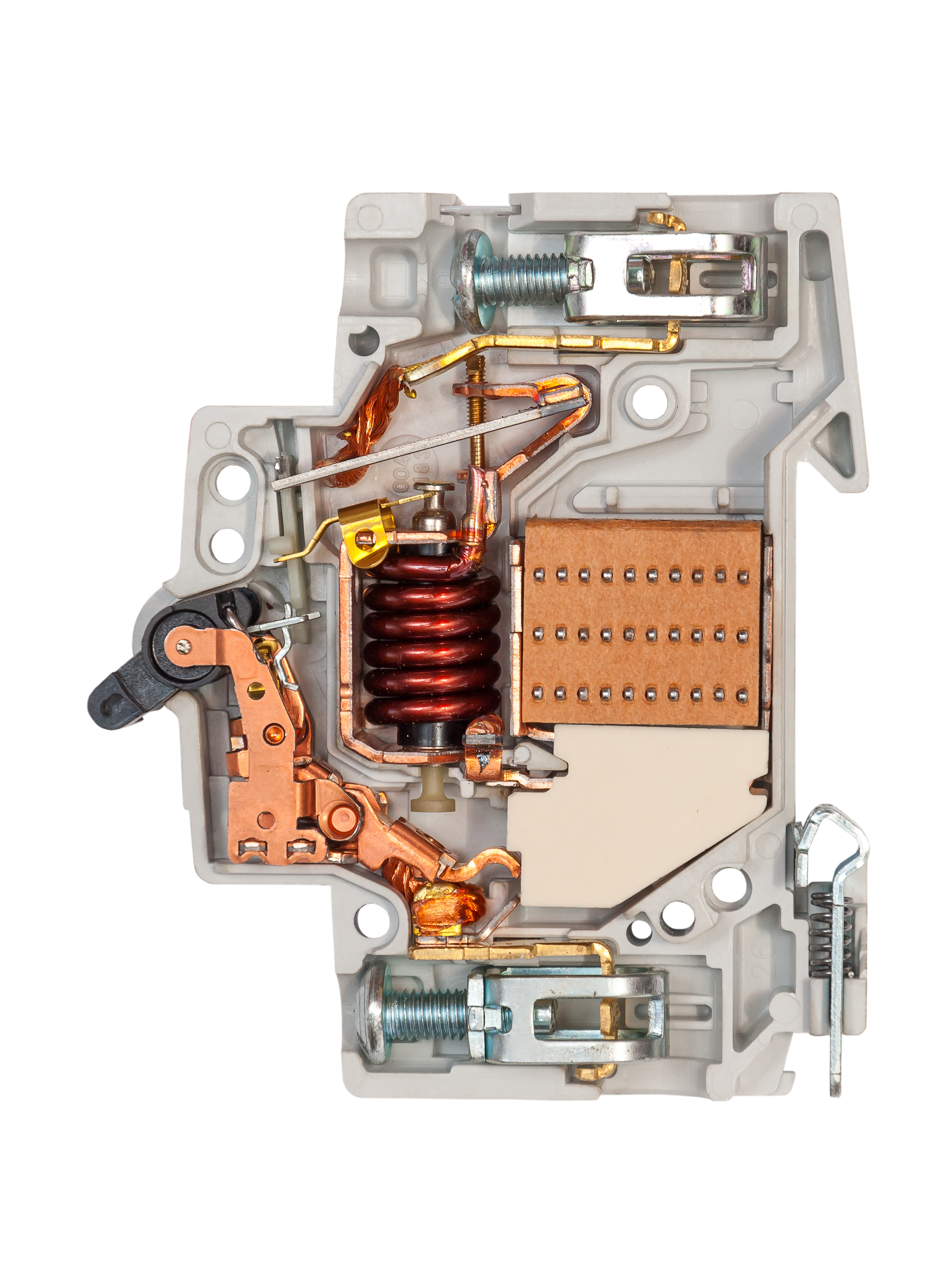
MCCB-internal-view
Circuit Breakers Types
Low Voltage, less than 600V
Molded-Case Circuit Breakers (MCCBs)

MCCB are the most widely used type of circuit breakers. They are available in a wide range of ratings and are generally used for low-current, low-energy power circuits. They can be found in residential, commercial, and industrial facilities. MCCB are simple mechanical devices which employ a thermal bimetallic element that has inverse time–current characteristics for overcurrent protection and a mechanical magnetic trip element for short-circuit protection

Demulsifi cation occurs when the tiny droplets unite to form larger drops, which sink to the bottom and form a pool of free water. Water in the free state may be readily removed by fi ltering or centrifugal treatment. However, dissolved water is not removed by centrifugal treatment

Insulated-Case Breakers

Insulated-case circuit breakers are a type of molded-case breaker constructed with glass reinforced insulating material for increased dielectric strength. These breakers can have Electromechanical trip units which was discussed above, or an Electronic trip units offer capabilities such as programming monitoring diagnostics communications system coordination and testing that are not available on thermal magnetic trip units.

Motor Circuit Protector (MCP)

Magnetic-trip-only breakers have no thermal element. Such breakers are principally only used for isolating the circuit and short-circuit protection. Molded-case breakers with magnetic only trips find their application in motor circuit protection. MCP's can be found inside Motor Control Center (MCC). They are typically placed inside a cubical or enclosure, along with motor control elements and a motor overcurrent device; commonly knows as a heater.

Fixed or Draw-Out Power Circuit Breakers

Heavy-duty power circuit breakers employ spring-operated, stored-energy mechanisms for quick-make, quick-break manual or electric operation. Generally, these breakers have draw-out features whereby individual breakers can be put into test and fully de-energized position for testing and maintenance purposes.
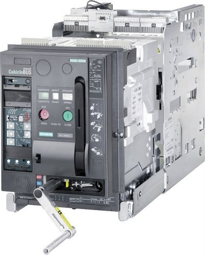
MCCB-internal-view
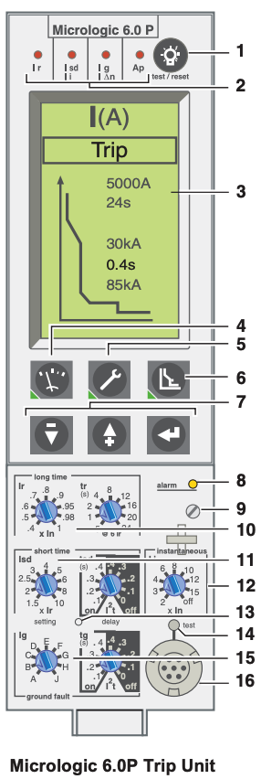
Electronic Trip
Low voltage Transformer nameplate
Circuit Breaker Manufacturers:
  1. General Electric
  2. Square D
  3. Eaton
  4. Siemens
  5. ABB
Voltage, Current, Frequency

15, 20, 25, 30, 35, 40, 45, 50, 60, 70, 80, 90,
100, 110, 125, 150, 175, 200, 225, 250, 300, 350, 400, 450, 500, 600, 700, 800,
1000, 1200, 1600, 2000, 2500, 3000, 4000 5000, and 6000 amps.

Additional standard fuse sizes are 1, 3, 6, 10, and 601 amps.

Industrial-grade MCCBs are available in frame sizes from 100 amperes to 3000 amperes. ICCBs are available in frame sizes from 400 to 5000 amperes. The 400-ampere-frame ICCB is typically the same size and cost as the 800-ampere frame but is equipped with smaller-ratio current sensors. PCBs are available in frame sizes from 800 to 5000 amperes.

Frame Ratings:

Ampere Frame [AF] it is the rating breaker current [maximum. current which the breaker will withstand for a long. time].

Ampere Ratings:

Ampere trip [AT] it is the current set to trip the. circuit [usually from 60% up to 100% of the AF]
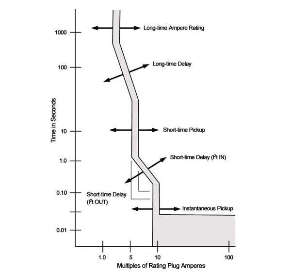
Electronic Trip Unit Protective Elements
Long Time
Pick up, (Ir)
Multiple of Breaker Frame Size, (xLn)

Pick Up Current

Long Time
Delay
Range Values Vary with Manufactures

Long time dif

Short Time
Pick Up:
Multiple of Long Time Pick up value, (STPU xIr)

Short-time Pickup refers to how strong the current surge must be for the breaker to switch from the long-time delay to the short-time delay. This setting is typically given as a multiple of the ampacity of the breaker; for example, if this value is set to 5 on a 200 A breaker, the short-time pickup occurs at 1,000 A. On the curve, the short-time pickup is represented by a vertical line between the long-time delay and short-time delay parts of the curve. Changing this value will move the line along the x-axis: Higher currents move the line right. Lower currents move the line left. The lengths of the long-time delay and short-time delay slopes will be affected accordingly.

Short Time
Delay:
Range Values Vary with Manufactures

Short-time delay refers to the length of time the breaker will allow stronger current surges before the breaker trips. The time may or may not be affected by the strength of the current, depending upon the I² T setting. On the curve, the short-time delay is represented by either a horizontal line or a slope to the right of the short-time pickup part of the curve. Changing this value will move the line along the y-axis: Faster trip times move the line down. Slower trip times move the line up.

I² T refers to the relationship between the strength of the current surge and the trip time for the breaker. Here, it specifically refers to whether the short-time delay is a variable based upon the strength of the current surge or a constant value. On the curve, this value determines whether the short-time delay is represented by a horizontal line or a slope: OUT: The trip time will not be affected by the current, and the short-time delay is shown as a horizontal line. IN: The trip time will be affected by the current, and the short-time delay is shown as a slope.

Instantaneous: Multiple of Breaker Frame Size (xLn)

Instantaneous Pickup refers to how strong the current surge must be for the breaker to trip immediately. For electronic breakers, this setting is typically given as a multiple of the ampacity of the breaker; for example, if this value is set to 15 on a 200 A breaker, the instantaneous pickup occurs at 3,000 A.

On the curve, the instantaneous pickup is represented by a vertical line and rectangular block on the rightmost part of the graph. Changing this value will move the line and block along the x-axis: Higher currents move the line and block right. Lower currents move the line and block left. If this is set to None, the instantaneous pickup will never occur, and the line and block will be removed from the graph.

Ground Fault
Pick up:
Multiple of Breaker Frame Size (xLn), with a maximum value of 1200A
Ground Fault
Delay:
Typical values are 0.1-0.5 seconds
TCC Curve
Article 100 Definitions
Neta Table 100.5
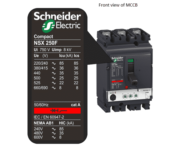
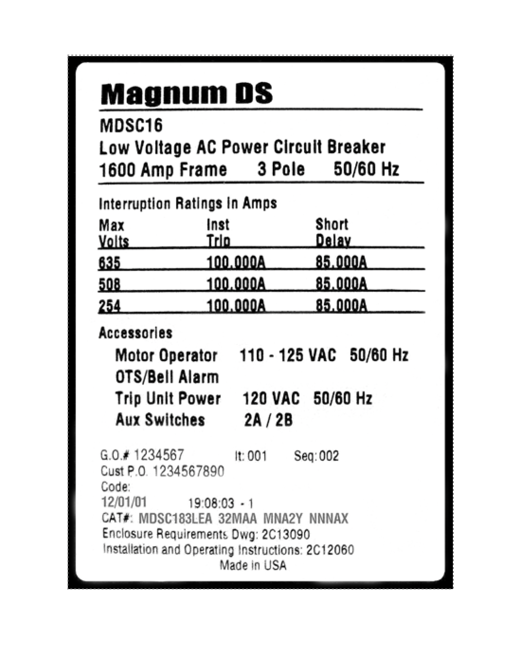
  1. Interrupting Rating: The highest current at rated voltage that a device is identified to interrupt under standard test conditions.
    • Ampere Interrupting Capacity (AIC)
    • Ampere Interrupt Rating (AIR)

    The short circuit rating of a circuit breaker is defined by its interrupting capacity 10K, 25K, 35K, 42K, 65K, 100K, 200KAIC

  2. Current overload and short circuit protection of electrical equipment.
  3. Overloading of electrical equipment, such as cables, can deteriorate insulation due to thermal stress cause by heat.
    As current increases past the cables design rating, insulation will begin to deteriorate. Over an extended period of time, leakage current will increase, eventually causing it to fail.

Auxilary Devices

  1. Electrical Operating Mechanisms:
  2. For electrical operation, MCCBs typically use a motor or solenoid operator to drive the handle mechanism. Motor operators have closing and opening times of several cycles to several seconds. Solenoid operators have operating times that vary from six cycles to several cycles. ICCBs and PCBs have internal motor operators that charge the closing springs within a few seconds. This charging time is independent of the circuit breaker closing and tripping time. The closing and tripping solenoid coils can close or open the circuit breaker in five or fewer cycles. Five-cycle closing is necessary.

Under Voltage

The undervoltage release instantaneously opens the circuit breaker when its supply voltage drops to a value between 35% and 70% of its rated voltage. If there is no supply to the release, it is impossible to close the circuit breaker, either manually or electrically. Any attempt to close the circuit breaker has no effect on the main contacts. Circuit breaker closing is enabled again when the supply voltage of the release returns to 85% of its rated value.

Energy Reduction Devices
Low Maintenance Mode

A circuit breaker equipped with Maintenance Mode can improve safety by providing a simple and reliable method to reduce fault clearing time. Work locations downstream of a circuit breaker with a Maintenance Mode unit can have a significantly lower incident energy level.

The energy-reducing maintenance switch is described in two sections of the 2017 National Electrical Code: article 240.87 for circuit breaker-protected circuits; and article 240.67 for fuse-protected circuits. In both cases, the function is identified as a method to reduce incident energy in circuits 1200A and larger.

The requirement in the 2017 NEC 240.87 is that if the normal instantaneous protection by the circuit breaker is not able to operate at the estimated arcing current, one of several additional protection methods must be included in the circuit. The energy-reducing maintenance switch is one of these prescribed methods. An additional requirement is that the function be provided with local status indication, though the code is not clear if local means the circuit breaker, or the load at the end of the conductors protected by the circuit breaker.

ARMS uses a separate electronic trip circuit providing faster signal processing and interruption times than the standard ‘instantaneous’ protection. When enabled, the trip unit will trip the breaker with no intentional delay whenever the configured pickup level is exceeded. When enabled, the Maintenance Mode function operates regardless of the instantaneous settings.

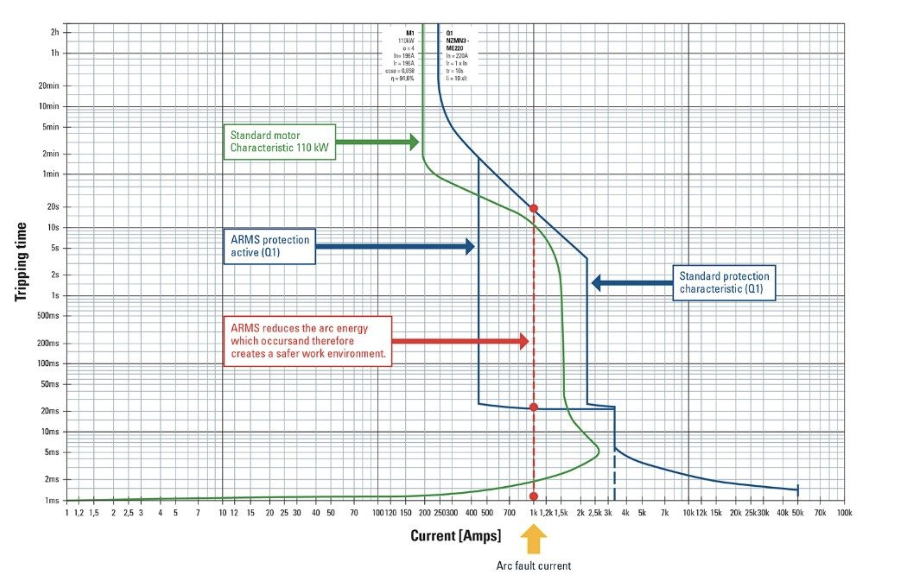
An activated ARMS function provides for faster triggering in case of overload. In the example above, the fault current is 1000A. The ARMS maintenance mode will cause the breaker to trip in 20ms instead of 20s.

Neta Table 100.5

An activated ARMS function provides for faster triggering in case of overload. In the example above, the fault current is 1000A. The ARMS maintenance mode will cause the breaker to trip in 20ms instead of 20s.

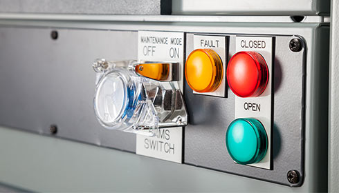
SQD Energy Reduction Maintenance Setting (ERMS) switch.
Continue reading
Energy Reduction Maintenance Setting (ERMS) switch.
The ERMS function is used to reduce the Ii protection settings in order to trip as fast as possible when a fault occurs. The pre-programmed factory setting for Ii protection in ERMS mode is 2xIn.
The ERMS switch can be turned “ON” to reduce circuit breaker tripping time. This sets the instantaneous pickup to a pre-programmed value; The default if not programmed = 2 x In
If the ERMS instantaneous pickup is adjusted to the same or lower setting than the short-time pickup, the instantaneous function will override the short-time function and trip the circuit breaker with no intentional delay.
Neta Table 100.5
Neta Table 100.5
GE Reduced Energy Let-Through (RELT)

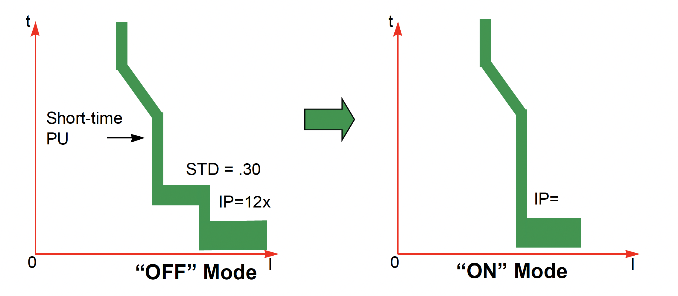
The concept behind the RELT function is not complex. In addition to the circuit breaker’s normal protection functions, there is a second instantaneous protection function with a dedicated threshold and algorithm optimized for speed and sensitivity. The user sets the threshold as needed, enables the function when required, and simply disables it when not required. Enabling or disabling the RELT function within any GE circuit breaker trip unit does not turn off or alter any other function; it enables or disables the faster instantaneous protection as seen in figure - 1. In every system, it should be possible to adjust

EATON Arcflash Reduction Maintenance System TM (ARMS)

ARMS uses a separate electronic trip circuit providing faster signal processing and interruption times than the standard ‘instantaneous’ protection. When enabled, the trip unit will trip the breaker with no intentional delay whenever the configured pickup level is exceeded. When enabled, the Maintenance Mode function operates regardless of the instantaneous settings.

Neta Table 100.5

An activated ARMS function provides for faster triggering in case of overload. In the example above, the fault current is 1000A. The ARMS maintenance mode will cause the breaker to trip in 20ms instead of 20s.

Series Rating

Series ratings permit the application of two or more circuit breakers in series, in accordance with the National Electrical Code (NEC) [16], at locations in a power system where the downstream circuit breaker interrupting capacity for an application that is not series-rated is lower than the available fault current. This is possible because both breakers share the high current fault interruption. Series-rated circuit breakers are UL tested as a combination of a fully rated upstream device, either a circuit breaker or a fuse, and a lower-rated downstream device. The upstream device in a series-rated system is always fully rated, with an interrupting capacity equal to the available fault current, while the downstream device may have a lower interrupting capacity. This allows a system design less costly than systems that use devices fully rated for the available fault current.

Zone Interlock

Zone-Selective Interlocking (ZSI), or zone restraint, has been available since the early 1990s. ZSI is designed to limit thermal stress caused by shortcircuits on a distribution system. ZSI will enhance the coordination of the upstream and downstream molded case circuit breakers for all values of available short-circuit current up to the instantaneous override of the upstream circuit breaker

Circuit breakers equipped with zone interlocking on short delay with no restraining signal from a downstream device will have the minimum time band applied regardless of setting, this is sometimes referred to as the maximum unrestrained delay. When the instantaneous function is disabled, a short-time delay override is used to instantaneously trip circuit breakers in the event of a significant short circuit. This is called the short-time withstand rating and is represented on the trip curve as an absolute ampere value.

Neutral CT
Kirk Interlock

A Kirk interlock is a keyed interlock. Each Kirk key has a serial number on it that must be matched to the tumbler. Only one key with the serial number should be in the substation. Kirk interlocks also are used to ensure proper sequences are followed in switching routines. Kirk interlocks can be used as a mechanical or electrical interlock. When used for electrical interlocking, the Kirk interlock operates an auxiliary switch. For example, a Kirk interlock could be used to ensure a transformer low side breaker is opened prior to opening a low side transformer disconnect switch. In this case, the Kirk key could only be removed from the low side transformer circuit breaker while it is in the open position. Then the Kirk key would be removed and placed in the matching serial number tumbler for the disconnect switch and turned, allowing the disconnect switch to be operated.

Circuit Breaker Tests
Test Equipment
  1. Primary Current Test Set
  2. Secondary Current Test set
  3. Insulation Resistance Test Set
  4. DLRO
Visual Mechanical Inspection:
  1. Clean all external contamination to permit internal heat dissipation.
  2. Inspect all surfaces for cracks or damage.
  3. Check for loose connections, and tighten circuit breaker terminals and bus bar connections. Use the manufacturer’s recommended torque values.
  4. Manually switch on and off the breaker in order to exercise the mechanism.
  5. Check for high-humidity conditions since high humidity will deteriorate the insulation system.
  6. Check for hot spots typically caused by overheating due to t ermination or connections being loose, high contact resistance, or inadequate ventilation.

  1. Features include:
  2. Additional Phase Protection Elements
    • Long-time
    • Short-time
    • Instantaneous
    • Ground-Fault
  3. Displayed Metering Capabilities
  4. Communication Capabilities
Pick up Test:

Continuous Amps (Ir) varies . Ir is a percentage of the circuit breaker’s nominal rating (In). Continuous amps can be adjusted from of the circuit breaker’s nominal rating.

Overcurrent Test:

The purpose of this test is to determine that the trip device will open the circuit breaker to which it is applied. This test can usually be performed by injecting 150%–300% current of the coil rating into the trip coil. The test equipment used should be able to produce the required current and be reasonably sinusoidal.

Short Time Test:

Circuit breaker short-time-delay (STD) mechanisms allow an intentional delay to be installed on low voltage power circuit breakers. Short-time-delays allow the fault current to flow for several cycles, which subjects the electrical equipment to unnecessarily high mechanical and thermal stress

Instantaneous Trip Test:

The magnetic (INST) trip should be checked by selecting suitable current to ensure that the breaker magnetic feature is working. The diffi culty in conducting this test is the availability of obtaining the required high value of test current.

Ground Fault Protection:

Zero Sequence

Circuit feeders are fed through a current transformer. A zero sequence relay or circuit breaker trip unit ensures that the circuit current feeding the load will return to the source returns on those same conductors . If the current is returning to the source through a different path (usually ground), the ground-fault relay will detect this difference. If the diffrence in current exceeds a pre-determined amount for a pre-determined amount of time, the ground-fault relay will operate.

Under normal operating condictions, the vector sum of the circuit currents should equal zero
Phase Currents + Neutral Currents = 0
\[I_{a}+I_{b}+I_{c}-I_{n}=0\]

Summation Method

Direct measurement of all phase and neutral current through a protection device's current transformers is evaluated. All phase currents feeding a load should return to the source. A ground fault some where downstream will create a difference in the returning current.

Phase Currents = Return Currents
\[I_{a}+I_{b}+I_{c}=I_{n}\]
Primary Current Test

Stationary and moving contacts are built from alloys that are formulated to endure the stresses of electrical arcing. However, if contacts are not maintained on a regular basis, their electrical resistance due to repeated arcing builds up, resulting in a signifi cant decrease in the contact’s ability to carry current. Excessive corrosion of contacts is detrimental to the breaker performance. One way to check contacts is to apply DC and measure the contact resistance or voltage drop across the closed contacts. The breaker contact resistance should be measured from bushing terminal to bushing terminal with the breaker in closed position.

Secondary Injectoon Testing

Solid-state trip units can be tested via secondary current injection using a test set specifically designed for the device to be tested. The main shortcoming of the secondary current injection test method is that only the solid-state trip unit logic and components are tested.

Unlike primary injection, this test method does not verify the current sensors, wiring, or circuit breaker current carrying components. This is the main reason why the primary injection test method has superiority over secondary injection testing.

No-Trip:

The protective functions of the electronic trip device can be tested, but the trip device won't send a trip signal to the circuit breakers trip actuator. This test can be performed while the circuit breaker is energized and carrying load current because a no-trip test won't cause the circuit breaker to open.

Trip Mode:

The protective functions of the electronic circuit are tested just like a no-trip mode test, except the trip unit will send a signal to the circuit breakers trip actuator. This will cause the circuit breaker to open, which is why this test is typically performed only when a circuit breaker is withdrawn from its compartment and therefore disconnected from the switchgear bus.

Contact Resistance

Stationary and moving contacts are built from alloys that are formulated to endure the stresses of electrical arcing. However, if contacts are not maintained on a regular basis, their electrical resistance due to repeated arcing builds up, resulting in a signifi cant decrease in the contact’s ability to carry current. Excessive corrosion of contacts is detrimental to the breaker performance. One way to check contacts is to apply DC and measure the contact resistance or voltage drop across the closed contacts. The breaker contact resistance should be measured from bushing terminal to bushing terminal with the breaker in closed position.

This is the primary circuit resistance test that was discussed in Section 8.7.2 for low-voltage power circuit breakers. This test consists of applying a DC across the closed circuit breaker contacts and measuring the voltage drop due to the contact resistance. Excessive voltage drop indicates abnormal conditions such as contact and/or connection erosion and contamination. This test is similar to the circuit breaker contact resistance measurement test described in Section 7.4.5 for medium-voltage breakers. The manufacturers of MCCBs should be consulted in order to fi nd the acceptable millivolt drop values for particular breakers being tested. It is recommended that large breakers be tested with DC of at least 100 A and smaller breakers be tested at rated (or below rated) currents. The measured values should be compared among three phases of the breaker under test, or with values of breakers of similar size or with manufacturer’s recommended values to assess whether the contacts need to be replaced or dressed.

Where:
  • \( {V_{Phase}: V_{Line-Line} , V_{Line-neutral} } \) \(\text{Phase voltage can be either Line to line or line to neutral}\)

Insulation Resistance:

DESCRIPTION:

This test is performed at or above rated voltage to determine if there are low resistance paths to ground or between winding to winding as a result of winding insulation deterioration.

PURPOSE:

This test is made to verify the condition of the insulation of the circuit breaker. A minimum of 1000 V test voltage should be used for low-voltage (600 V class) breakers for making this test. It would be preferable to use a DC test voltage that is at least 1.5–1.6 times the peak AC voltage of the circuit breaker. Tests should be made between pole to ground, between adjacent poles with circuit breaker contacts closed, and between phase-to-load terminal with breaker in open position. A minimum value of 1 MΩ is considered safe to prevent a fl ashover. Resistance values below 1 MΩ should be investigated for possible trouble.

Megohmmeter reading should be maintained for a period of 1 min. Make the following readings :
  1. A-phase line-side to A-phase load-side
  2. B-phase line-side to B-phase load-side
  3. C-phase line-side to C-phase load-side
EATON +310

ND, CND, HND, CHND, CNDC Equipped with Type NES Digitrip RMS 310 Trip units with I2T Ramp Short Time Delay (Phase Protection)

NETA Test Procedure

NETA ATS

7.6.1.1 Circuit Breakers, Air, Insulated-Case/Molded-Case

A. Visual and Mechanical Inspection:
  1. Compare equipment nameplate data with drawings and specifications.
  2. Inspect physical and mechanical condition.
  3. Inspect anchorage and alignment.
  4. Verify the unit is clean.
  5. Operate the circuit breaker to insure smooth operation.
  6. Inspect bolted electrical connections for high resistance using one or more of the following methods:
    1. Use of a low-resistance ohmmeter in accordance with Section 7.6.1.1.B.1.
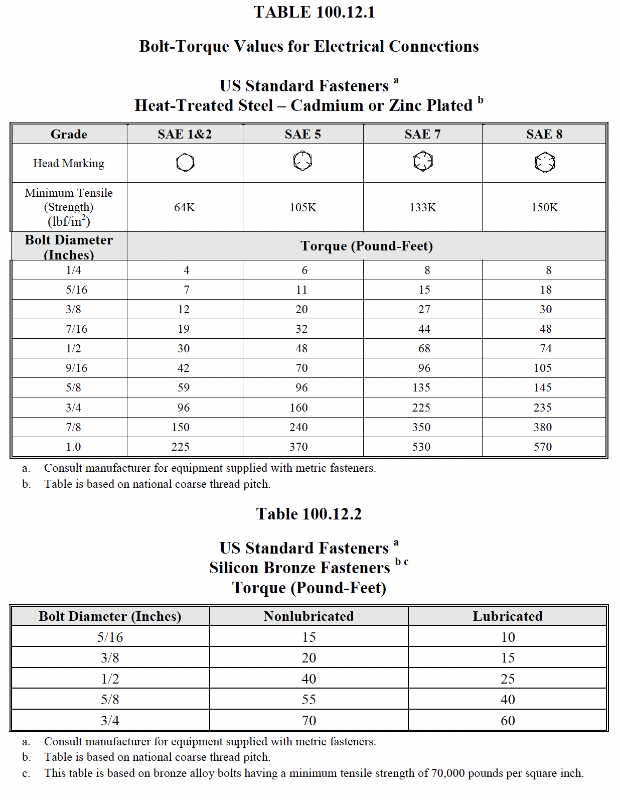
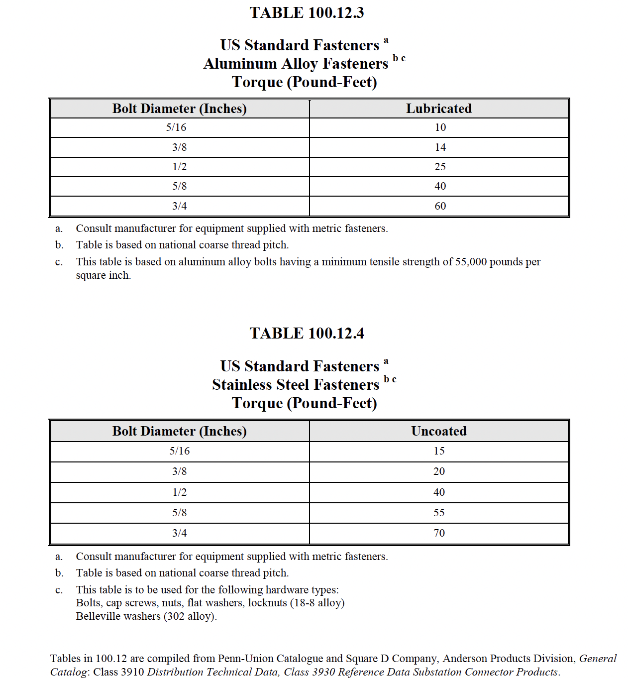
    2. Verify tightness of accessible bolted electrical connections by calibrated torquewrench method in accordance with manufacturer’s published data or Table 100.12.
    3. Perform thermographic survey in accordance with Section 9.
  7. Inspect operating mechanism, contacts, and arc chutes in unsealed units.
  8. Perform adjustments for final protective device settings in accordance with the coordination study.
B. Electrical Tests:
  1. Perform resistance measurements through bolted connections with a low-resistance ohmmeter, if applicable, in accordance with Section 7.6.1.1.A.6.1.
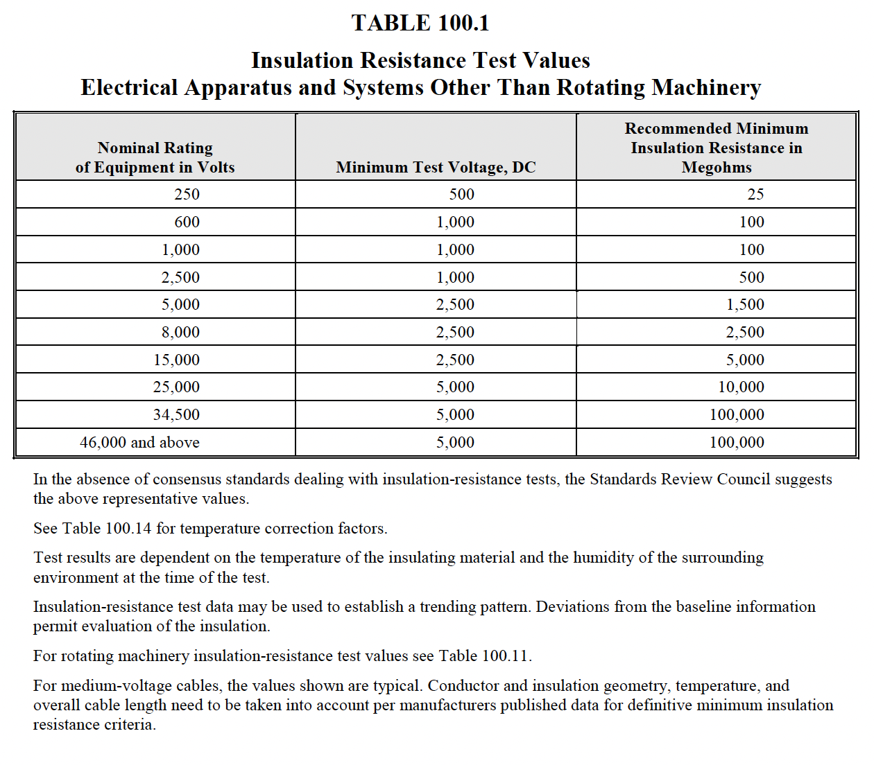
  2. Perform insulation-resistance tests for one minute on each pole, phase-to-phase and phase-toground with the circuit breaker closed, and across each open pole. Apply voltage in accordance with manufacturer’s published data. In the absence of manufacturer’s published data, use Table 100.1.
  3. Perform a contact/pole-resistance test.
  4. *Perform insulation-resistance tests on all control wiring with respect to ground. Applied potential shall be 500 volts dc for 300-volt rated cable and 1000 volts dc for 600-volt rated cable. Test duration shall be one minute. For units with solid-state components, follow manufacturer’s recommendation.
  5. Determine long-time pickup and delay by primary current injection.
  6. Determine short-time pickup and delay by primary current injection.
  7. Determine ground-fault pickup and time delay by primary current injection.
  8. Determine instantaneous pickup by primary current injection.
  9. *Test functions of the trip unit by means of secondary injection.
  10. Perform minimum pickup voltage tests on shunt trip and close coils in accordance with manufacturer’s published data.
  11. Verify correct operation of auxiliary features such as trip and pickup indicators, zone interlocking, electrical close and trip operation, trip-free, anti-pump function, and trip unit battery condition. Reset all trip logs and indicators.
  12. Verify operation of charging mechanism.
C. Test Values – Visual and Mechanical
  1. Compare bolted connection resistance values to values of similar connections. Investigate values which deviate from those of similar bolted connections by more than 50 percent of the lowest value. (7.6.1.1.A.6.1)
  2. Bolt-torque levels shall be in accordance with manufacturer’s published data. In the absence of manufacturer’s published data, use Table 100.12. (7.6.1.1.A.6.2)
  3. Results of the thermographic survey shall be in accordance with Section 9. (7.6.1.1.A.6.3)
  4. Settings shall comply with coordination study recommendations. (7.6.1.1.A.8)
D. Test Values – Electrical
  1. Compare bolted connection resistance values to values of similar connections. Investigate values which deviate from those of similar bolted connections by more than 50 percent of the lowest value.
  2. Insulation-resistance values shall be in accordance with manufacturer’s published data. In the absence of manufacturer’s published data, use Table 100.1. Values of insulation resistance less than this table or manufacturer’s recommendations should be investigated.
  3. Microhm or dc millivolt drop values shall not exceed the high levels of the normal range as indicated in the manufacturer’s published data. If manufacturer’s published data is not available, investigate values that deviate from adjacent poles or similar breakers by more than 50 percent of the lowest value.
  4. Insulation-resistance values of control wiring shall not be less than two megohms.
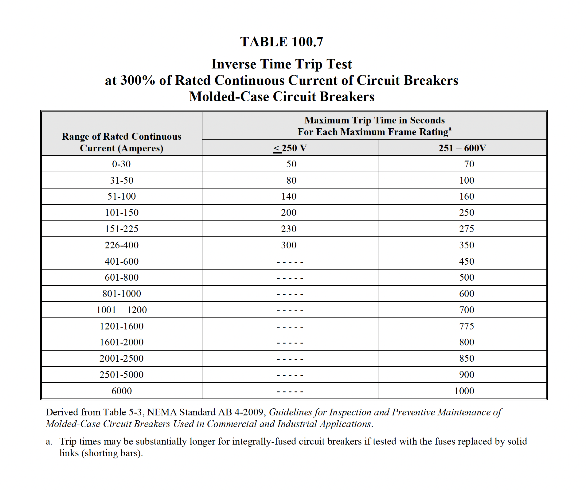
  5. Long-time pickup values shall be as specified, and the trip characteristic shall not exceed manufacturer’s published time-current characteristic tolerance band, including adjustment factors. If manufacturer’s curves are not available, trip times shall not exceed the value shown in Table 100.7.
  6. Short-time pickup values shall be as specified, and the trip characteristic shall not exceed manufacturer’s published time-current tolerance band.
  7. Ground fault pickup values shall be as specified, and the trip characteristic shall not exceed manufacturer’s published time-current tolerance band.
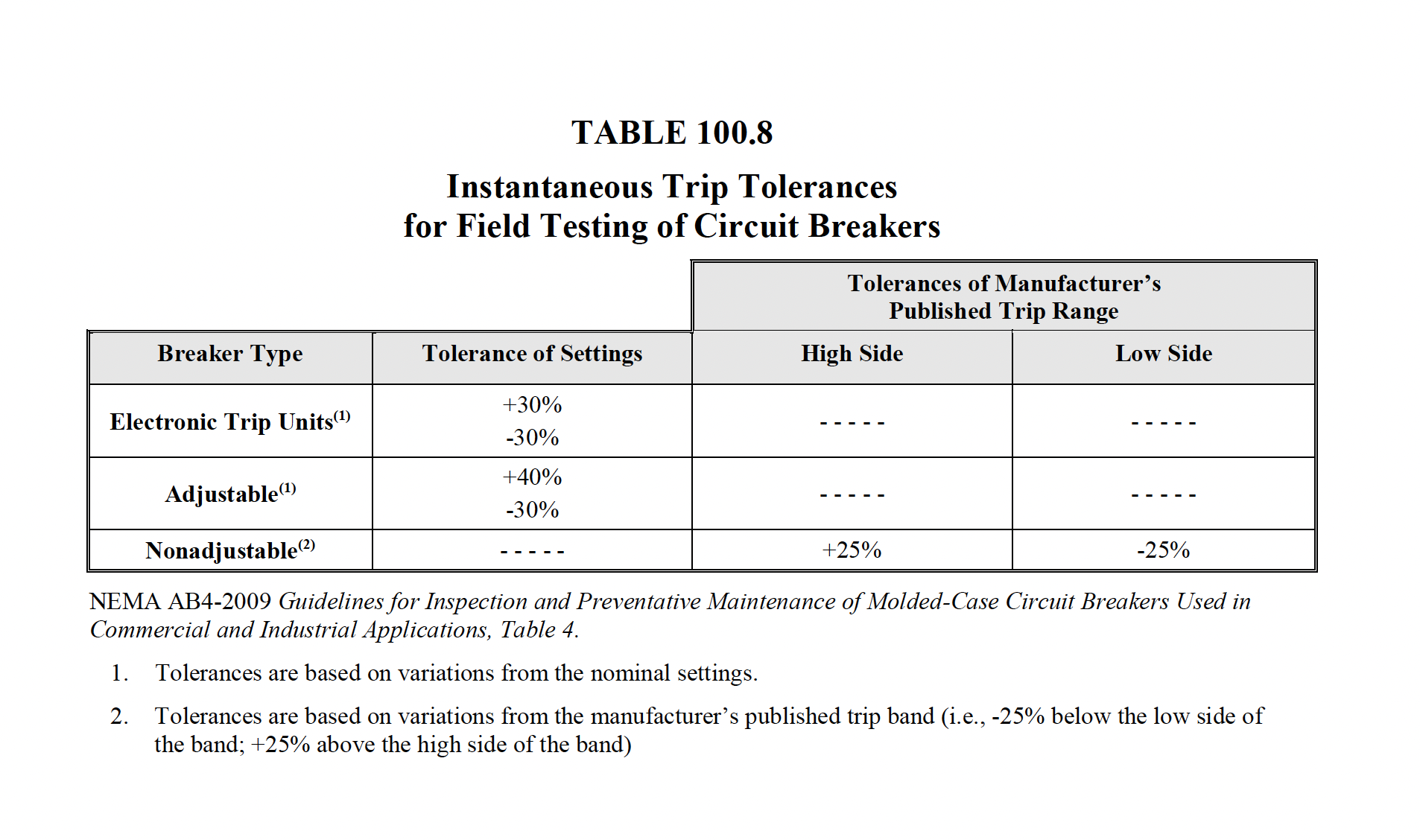
  8. Instantaneous pickup values shall be as specified and within manufacturer’s published tolerances. In the absence of manufacturer’s published data, refer to Table 100.8.
  9. Pickup values and trip characteristics shall be within manufacturer’s published tolerances.
  10. Minimum pickup voltage of the shunt trip and close coils shall conform to the manufacturer’s published data. In the absence of the manufacturer’s published data, refer to Table 100.20.
  11. Breaker open, close, trip, trip-free, anti-pump, and auxiliary features shall function as designed.
  12. The charging mechanism shall operate in accordance with manufacturer’s published data.

NETA ATS

7.6.1.2 Circuit Breakers, Low-Voltage Power

A. Visual and Mechanical Inspection:
  1. Compare equipment nameplate data with drawings and specifications.
  2. Inspect physical and mechanical condition.
  3. Inspect anchorage, alignment, and grounding.
  4. Verify that all maintenance devices are available for servicing and operating the breaker.
  5. Verify the unit is clea
  6. Verify the arc chutes are intact.
  7. Inspect moving and stationary contacts for condition and alignment.
  8. Verify that primary and secondary contact wipe and other dimensions vital to satisfactory operation of the breaker are correct.
  9. Perform all mechanical operator and contact alignment tests on both the breaker and its operating mechanism in accordance with manufacturer’s published data.
  10. Inspect bolted electrical connections for high resistance using one or more of the following methods:
    1. Use of a low-resistance ohmmeter in accordance with Section 7.6.1.2.B.1.
    2. Verify tightness of accessible bolted electrical connections by calibrated torquewrench method in accordance with manufacturer’s published data or Table 100.12.
    3. Perform a thermographic survey in accordance with Section 9.
  11. Verify cell fit and element alignment.
  12. Verify racking mechanism operation.
  13. Verify appropriate lubrication on moving current-carrying parts and on moving and sliding surfaces.
  14. Perform adjustments for final protective device settings in accordance with coordination study provided by end user.
  15. Record as-found and as-left operation counter readings.
B. Electrical Tests:
  1. Perform resistance measurements through bolted connections with a low-resistance ohmmeter, if applicable, in accordance with Section 7.6.1.2.A.10.1.
  2. Perform insulation-resistance tests for one minute on each pole, phase-to-phase and phase-toground with the circuit breaker closed, and across each open pole. Test voltage shall be in accordance with manufacturer’s published data. In the absence of manufacturer’s published data, use Table 100.1.
  3. Perform a contact/pole-resistance test.
  4. Perform insulation-resistance tests on all control wiring with respect to ground. Applied potential shall be 500 volts dc for 300-volt rated cable and 1000 volts dc for 600-volt rated cable. Test duration shall be one minute. For units with solid-state components, follow manufacturer’s recommendation.
  5. Determine long-time pickup and delay by primary current injection.
  6. Determine short-time pickup and delay by primary current injection.
  7. Determine ground-fault pickup and delay by primary current injection.
  8. Determine instantaneous pickup value by primary current injection.
  9. *Test functions of the trip unit by means of secondary injection.
  10. Perform minimum pickup voltage tests on shunt trip and close coils in accordance with manufacturer’s published data.
  11. Verify correct operation of any auxiliary features such as trip and pickup indicators, zone interlocking, electrical close and trip operation, trip-free, antipump function, and trip unit battery condition. Reset all trip logs and indicators.
  12. Verify operation of charging mechanism.
C. Test Values – Visual and Mechanical
  1. Compare bolted connection resistance values to values of similar connections. Investigate values which deviate from those of similar bolted connections by more than 50 percent of the lowest value. (7.6.1.2.A.10.1).
  2. Bolt-torque levels shall be in accordance with manufacturer’s published data. In the absence of manufacturer’s published data, use Table 100.12. (7.6.1.2.A.10.2)
  3. Results of the thermographic survey shall be in accordance with Section 9. (7.6.1.2.A.10.3)
  4. Settings shall comply with coordination study recommendations. (7.6.1.2.A.14)
  5. Operations counter shall advance one digit per close-open cycle. (7.6.1.2.A.15)
D. Test Values – Electrical
  1. Compare bolted connection resistance values to values of similar connections. Investigate values which deviate from those of similar bolted connections by more than 50 percent of the lowest value.
  2. Insulation-resistance values of circuit breakers shall be in accordance with manufacturer’s published data. In the absence of manufacturer’s published data, use Table 100.1. Values of insulation resistance less than this table or manufacturer’s recommendations should be investigated.
  3. Microhm or dc millivolt drop values shall not exceed the high levels of the normal range as indicated in the manufacturer’s published data. In the absence of manufacturer’s published data, investigate values that deviate from adjacent poles or similar breakers by more than 50 percent of the lowest value
  4. Insulation-resistance values of control wiring shall not be less than two megohms.
  5. Long-time pickup values shall be as specified, and the trip characteristic shall not exceed manufacturer’s published time-current characteristic tolerance band, including adjustment factors. If manufacturer’s curves are not available, trip times shall not exceed the value shown in Table 100.7.
  6. Short-time pickup values shall be as specified, and the trip characteristic shall not exceed manufacturer’s published time-current tolerance band.
  7. Ground fault pickup values shall be as specified, and the trip characteristic shall not exceed manufacturer’s published time-current tolerance band.
  8. Instantaneous pickup values shall be as specified and within manufacturer’s published tolerances. In the absence of manufacturer’s published data, refer to Table 100.8.
  9. Pickup values and trip characteristic shall be as specified and within manufacturer’s published tolerances.
  10. Minimum pickup voltage of the shunt trip and close coils shall conform to the manufacturer’s published data. In the absence of the manufacturer’s published data, refer to Table 100.20.
  11. Auxiliary features shall operate in accordance with manufacturer’s published data.
  12. The charging mechanism shall operate in accordance with manufacturer’s published data.

NETA MTS

7.6.1.1 Circuit Breakers, Air, Insulated-Case/Molded-Case

A. Visual and Mechanical Inspection:
  1. Inspect physical and mechanical condition.
  2. Inspect anchorage and alignment.
  3. Prior to cleaning the unit, perform as-found tests, if required.
  4. Clean the unit.
  5. Operate the circuit breaker to ensure smooth operation.
  6. Inspect bolted electrical connections for high resistance using one or more of the following methods:
    1. Use of a low-resistance ohmmeter in accordance with Section 7.6.1.1.B.1.
    2. Verify tightness of accessible bolted electrical connections by calibrated torquewrench method in accordance with manufacturer’s published data or Table 100.12.
    3. Perform thermographic survey in accordance with Section 9.
  7. Inspect operating mechanism, contacts, and arc chutes in unsealed units.
  8. Perform adjustments for final protective device settings in accordance with coordination study provided by end user.
  9. Perform as-left tests.
B. Electrical Tests:
  1. Perform resistance measurements through bolted connections with a low-resistance ohmmeter in accordance with Section 7.6.1.1.A.6.1.
  2. Perform insulation-resistance tests for one minute on each pole, phase-to-phase and phaseto- ground with the circuit breaker closed, and across each open pole. Apply voltage in accordance with manufacturer’s published data. In the absence of manufacturer’s published data, use Table 100.1.
  3. Perform a contact/pole-resistance test.
  4. *Perform insulation-resistance tests on all control wiring with respect to ground. The applied potential shall be 500 volts dc for 300-volt rated cable and 1000 volts dc for 600-volt rated cable. Test duration shall be one minute. For units with solid-state components, follow manufacturer’s recommendation.
  5. Determine long-time pickup and delay by primary current injection.
  6. Determine short-time pickup and delay by primary current injection.
  7. Determine ground-fault pickup and time delay by primary current injection.
  8. Determine instantaneous pickup by primary current injection.
  9. *Test functions of the trip unit by means of secondary injection.
  10. Perform minimum pickup voltage test on shunt trip and close coils in accordance with Table 100.20.
  11. Verify correct operation of auxiliary features such as trip and pickup indicators, zone interlocking, electrical close and trip operation, trip-free, anti-pump function, and trip unit battery condition. Reset all trip logs and indicators.
  12. Reset all trip logs and indicators.
  13. Verify operation of charging mechanism.
C. Test Values – Visual and Mechanical
  1. Compare bolted connection resistance values to values of similar connections. Investigate values which deviate from those of similar bolted connections by more than 50 percent of the lowest value. (7.6.1.1.A.6.1)
  2. Bolt-torque levels should be in accordance with manufacturer’s published data. In the absence of manufacturer’s published data, use Table 100.12. (7.6.1.1.A.6.2)
  3. Results of the thermographic survey shall be in accordance with Section 9. (7.6.1.1.A.6.3)
  4. Settings shall comply with coordination study recommendations. (7.6.1.1.A.8)
D. Test Values – Electrical
  1. Compare bolted connection resistance values to values of similar connections. Investigate values which deviate from those of similar bolted connections by more than 50 percent of the lowest value.
  2. Insulation-resistance values should be in accordance with manufacturer’s published data. In the absence of manufacturer’s published data, use Table 100.1. Values of insulation resistance less than this table or manufacturer’s recommendations should be investigated.
  3. Microhm or dc millivolt drop values should not exceed the high levels of the normal range as indicated in the manufacturer’s published data. If manufacturer’s data is not available, investigate values that deviate from adjacent poles or similar breakers by more than 50 percent of the lowest value.
  4. Insulation-resistance values of control wiring should be comparable to previously obtained results but not less than two megohms.
  5. Long-time pickup values should be as specified, and the trip characteristic should not exceed manufacturer’s published time-current characteristic tolerance band, including adjustment factors. If manufacture
  6. Short-time pickup values shall be as specified, and the trip characteristic shall not exceed manufacturer’s published time-current tolerance band.
  7. Ground fault pickup values shall be as specified, and the trip characteristic shall not exceed manufacturer’s published time-current tolerance band.
  8. Instantaneous pickup values shall be as specified and within manufacturer’s published tolerances. In the absence of manufacturer’s published data, refer to Table 100.8.
  9. Pickup values and trip characteristics shall be within manufacturer’s published tolerances.
  10. Minimum pickup voltage of the shunt trip and close coils shall conform to the manufacturer’s published data. In the absence of the manufacturer’s published data, refer to Table 100.20.
  11. Breaker open, close, trip, trip-free, anti-pump, and auxiliary features shall function as designed.
  12. Trip logs and indicators are reset.
  13. The charging mechanism shall operate in accordance with manufacturer’s published data.

NETA ATS

7.6.1.2 Circuit Breakers, Low-Voltage Power

A. Visual and Mechanical Inspection:
  1. Inspect physical and mechanical condition.
  2. Inspect anchorage, alignment, and grounding.
  3. Verify that all maintenance devices are available for servicing and operating the breaker.
  4. Prior to cleaning the unit, perform as-found tests, if required.
  5. Clean the unit.
  6. Inspect arc chutes.
  7. Inspect moving and stationary contacts for condition and alignment.
  8. Verify that primary and secondary contact wipe and other dimensions vital to satisfactory operation of the breaker are in accordance with manufacturer’s published data.
  9. Perform all mechanical operator and contact alignment tests on both the breaker and its operating mechanism in accordance with manufacturer’s published data.
  10. Inspect bolted electrical connections for high resistance using one or more of the following methods:
    1. Use of a low-resistance ohmmeter in accordance with Section 7.6.1.2.B.1.
    2. Verify tightness of accessible bolted electrical connections by calibrated torquewrench method in accordance with manufacturer’s published data or Table 100.12.
    3. Perform a thermographic survey in accordance with Section 9.
  11. Verify cell fit and element alignment.
  12. Verify racking mechanism operation.
  13. Verify appropriate lubrication on moving current-carrying parts and on moving and sliding surfaces.
  14. Perform adjustments for final protective device settings in accordance with coordination study provided by end user.
  15. Perform as-left tests.
  16. Record as-found and as-left operation counter readings.
B. Electrical Tests:
  1. Perform resistance measurements through bolted connections with a low-resistance ohmmeter, if applicable, in accordance with Section 7.6.1.2.A.10.1.
  2. Perform insulation-resistance tests for one minute on each pole, phase-to-phase and phase-toground with the circuit breaker closed, and across each open pole. Test voltage shall be in accordance with manufacturer’s published data. In the absence of manufacturer’s published data, use Table 100.1.
  3. Perform a contact/pole-resistance test.
  4. Perform insulation-resistance tests on all control wiring with respect to ground. Applied potential shall be 500 volts dc for 300-volt rated cable and 1000 volts dc for 600-volt rated cable. Test duration shall be one minute. For units with solid-state components, follow manufacturer’s recommendation.
  5. Determine long-time pickup and delay by primary current injection.
  6. Determine short-time pickup and delay by primary current injection.
  7. Determine ground-fault pickup and delay by primary current injection.
  8. Determine instantaneous pickup value by primary current injection.
  9. *Test functions of the trip unit by means of secondary injection.
  10. Perform minimum pickup voltage test on shunt trip and close coils in accordance with manufacturer’s published data. In the absence of manufacturer’s published data, refer to Table 100.20.
  11. Verify correct operation of auxiliary features such as trip and pickup indicators, zone interlocking, electrical close and trip operation, trip-free, antipump function, and trip unit battery condition.
  12. Reset all trip logs and indicators.
  13. Verify operation of charging mechanism.
C. Test Values – Visual and Mechanical
  1. Compare bolted connection resistance values to values of similar connections. Investigate values which deviate from those of similar bolted connections by more than 50 percent of the lowest value. (7.6.1.2.A.10.1).
  2. Bolt-torque levels shall be in accordance with manufacturer’s published data. In the absence of manufacturer’s published data, use Table 100.12. (7.6.1.2.A.10.2)
  3. Results of the thermographic survey shall be in accordance with Section 9. (7.6.1.2.A.10.3)
  4. Settings shall comply with coordination study recommendations. (7.6.1.2.A.15)
  5. Operations counter shall advance one digit per close-open cycle. (7.6.1.2.A.16)
D. Test Values – Electrical
  1. Compare bolted connection resistance values to values of similar connections. Investigate values which deviate from those of similar bolted connections by more than 50 percent of the lowest value.
  2. Insulation-resistance values of circuit breakers shall be in accordance with manufacturer’s published data. In the absence of manufacturer’s published data, use Table 100.1. Values of insulation resistance less than this table or manufacturer’s recommendations should be investigated.
  3. Microhm or dc millivolt drop values shall not exceed the high levels of the normal range as indicated in the manufacturer’s published data. In the absence of manufacturer’s published data, investigate values that deviate from adjacent poles or similar breakers by more than 50 percent of the lowest value
  4. Insulation-resistance values of control wiring shall not be less than two megohms.
  5. LLong-time pickup values should be as specified, and the trip characteristic shall not exceed manufacturer’s published time-current characteristic tolerance band.
  6. Short-time pickup values shall be as specified, and the trip characteristic shall not exceed manufacturer’s published time-current tolerance band.
  7. Ground fault pickup values shall be as specified, and the trip characteristic shall not exceed manufacturer’s published time-current tolerance band.
  8. Instantaneous pickup values should be within the tolerances of manufacturer’s published data.
  9. Pickup values and trip characteristic shall be as specified and within manufacturer’s published tolerances.
  10. Minimum pickup voltage of the shunt trip and close coils shall conform to the manufacturer’s published data. In the absence of the manufacturer’s published data, refer to Table 100.20.
  11. Auxiliary features shall operate in accordance with manufacturer’s published data.
  12. Trip logs and indicators are reset.
  13. The charging mechanism should operate in accordance with manufacturer’s published data.
NETA ATS / MTS
TABLE 100.1
Neta Table 100.5
NETA ATS / MTS
TABLE 100.7
Neta Table 100.7
NETA ATS / MTS
TABLE 100.8
Neta Table 100.5
NETA ATS / MTS
TABLE 100.12
Neta Table 100.5 Neta Table 100.5
NETA ATS / MTS
TABLE 100.20
Neta Table 100.5 Neta Table 100.5