SIDEBAR SKINS

HEADER SKINS

Total Collections
Grounding Resistance Test
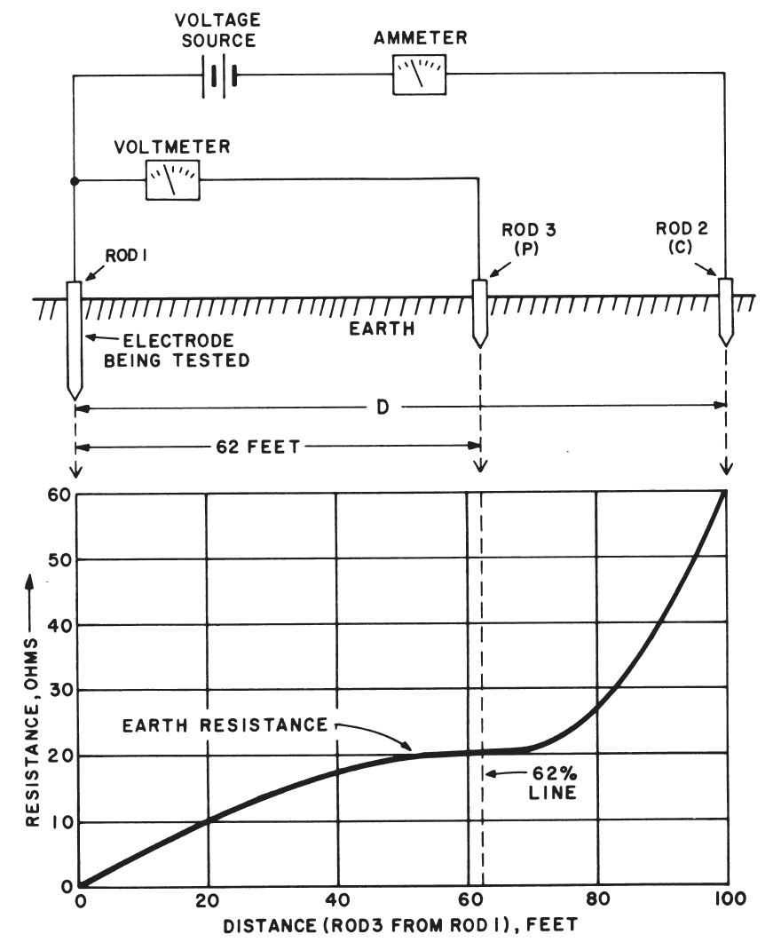
Fall of Potential Test

NEC Requirements and UL Standards

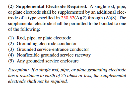
The National Electric Code under Article 250.53 (A.2)
Low Voltage Switch with integrated GFI relay
  1. Establishes a requirement for a single ground rod or ground plate to have an earth resistance of 25 ohms or less.
  2. Fall of Potentioal Test can be perfomered using a ground resitance test set to determin the "Fall-of-potential" between the rod being tested and the reference rod (stake) connected to the terminal of the tester.
  3. "Clamp-on" ground resistance tester is a simpler method of testing the earth resistance of a grounding electrode

IEEE 142, “IEEE Recommended Practice for Grounding of Industrial and Commercial Power Systems”

  1. IEEE 142 Recommends an earth resistance value in the range of 1/2 to 5 ohms.

IEEE 80

  1. For generating plants and large substations, IEEE 80 recommends grounding has values of 1/2 to 1 ohm

IEEE 81

“Three Point Fall-of Potential”

  1. Fall-of-Potential method are adequate for systems that are relatively small and have a required earth resistance of greater than 1 ohm

IEEE 81.2

  1. For large grids and systems requiring a ground resistance of less than 1 ohm, the IEEE 81.2 standard should be considered
Transformer Types
Low Voltage, Greater than 600V
Grounding
  • Grounding of electrical equipment serves several purposes. The first is to protect personnel and equipment from overvoltages, faults and lightning. Grounding also ensures stability of system voltages by providing a solid reference to earth, and establishes a reference to control electrical “noise” that might interfere with the proper operation of electronic equipment. Acurate measure of a facility's ground resistance is essential in preventing costly downtime due to service interruptions caused by poor grounds.

Soil Resistivity
  • Soil resistivity directly imapacts the resistance or performance of an electrical grounding system. It is also the starting point of any electrical grounding design.
    A well designed ground system ensures that protective devices will operate correctly during a fault event and reduce any excessive voltages developed during a fault, which could damage equipment and endanger the safety of anyone near the fault.

4-Point Test
  • Prior to installing a ground system the resistivity of the surrounding soil should be measured. Inaccurate resistivity tests can lead to unnecessary costs in additional system design and construction costs. After installation it is vital to check that the electrical grounding system meets the design criteria and should be measured periodically to ensure corrosion or changes in the soil's resistivity do not have an adverse effect. Ground networks may not appear faulty until a fault occurs and a dangerous situation arises.

Fall of Potential (3-point Method)
DESCRIPTION:

This method measures grounding electrode resistance based upon the principle of potential drop across the resistance.

There are three basic types of the Fall-of-Potential test methods and a number of related test methods that will be described in the appendices.
The types of Fall-of-Potential are:

  1. Fall-of-Potential

    A number of tests are made at different spaces of P and the resistance curve is plotted.

  2. Simplified Fall-of-Potential

    three measurements are made at defined distances of P and mathematical calculations are used to determine the resistance (to be described in more detail later).

  3. 61.8% Rule

    a single measurement is made with P at a distance 61.8% (62%) of the distance between the electrode under test and C.

The related test methods tend to be more complex and sophisticated requiring many measurements and/or a great deal of math. These methods have been developed to help overcome the problems faced when testing large ground systems or when there is limited space. A list of these methods follows:

  1. Intersecting curves method (Appendix IV)
  2. Slope method (Appendix V)
  3. Four-potential method (Appendix VI)
  4. Star delta method (Appendix VII)
PROCEDURE:
Test Item
  • ROD 1 : Ground Electrode Under Test
  • ROD 2 (C): Current Rod or Test set Voltage Source Lead
  • ROD 3 (P) : Potential Rod
Test Procedures
  1. The earth electrode of interest must be disconnected from its connection to the site.

  2. Connect Test set to the earth electrode (ROD 1).

  3. Two earth stakes are placed in the soil in a direct line—away from the earth electrode. Normally, spacing of 20 meters (65 feet) is sufficient. For more detail on placing the stakes, see the next section.

  4. A known current is generated by a poratbel test set between the outer stake (auxiliary earth stake) and the earth electrode, while the drop in voltage potential is measured between the inner earth stake and the earth electrode. Using Ohm's Law (V = IR), the tester automatically calculates the resistance of the earth electrode.

  5. Correct earth resistance is read from the curve for the distance that is about 62 percent of the total distance from the earth electrode to C. In other words, if the total distance is D, the 62 percent distance is 0.62D; for example, if D is 120 ft, the distance value for earth resistance is 0.62 x 120 or 74 ft.

Figure 1(a)

Neta Table 100.5

Figure 1(b)

NETA MTS TABLE 100.5
Insulation Resistance Test Values
Electrical Apparatus and Systems Other Than Rotating Machinery
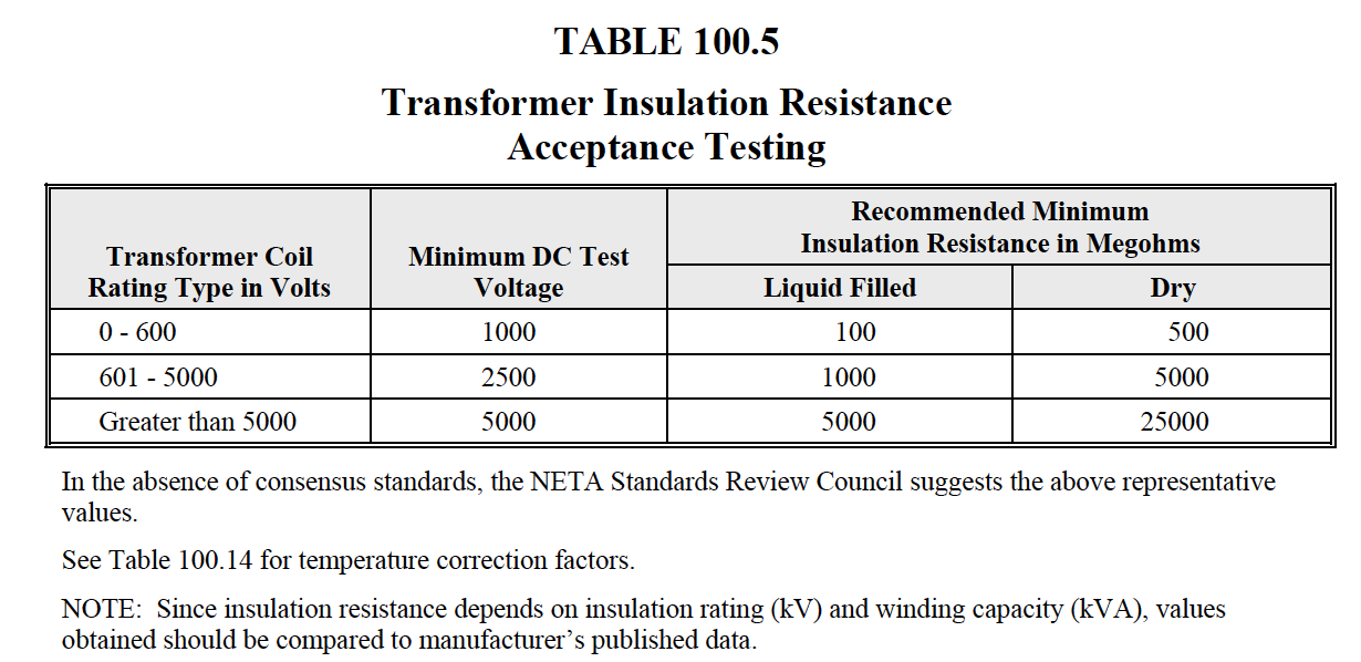
Neta Table 100.5
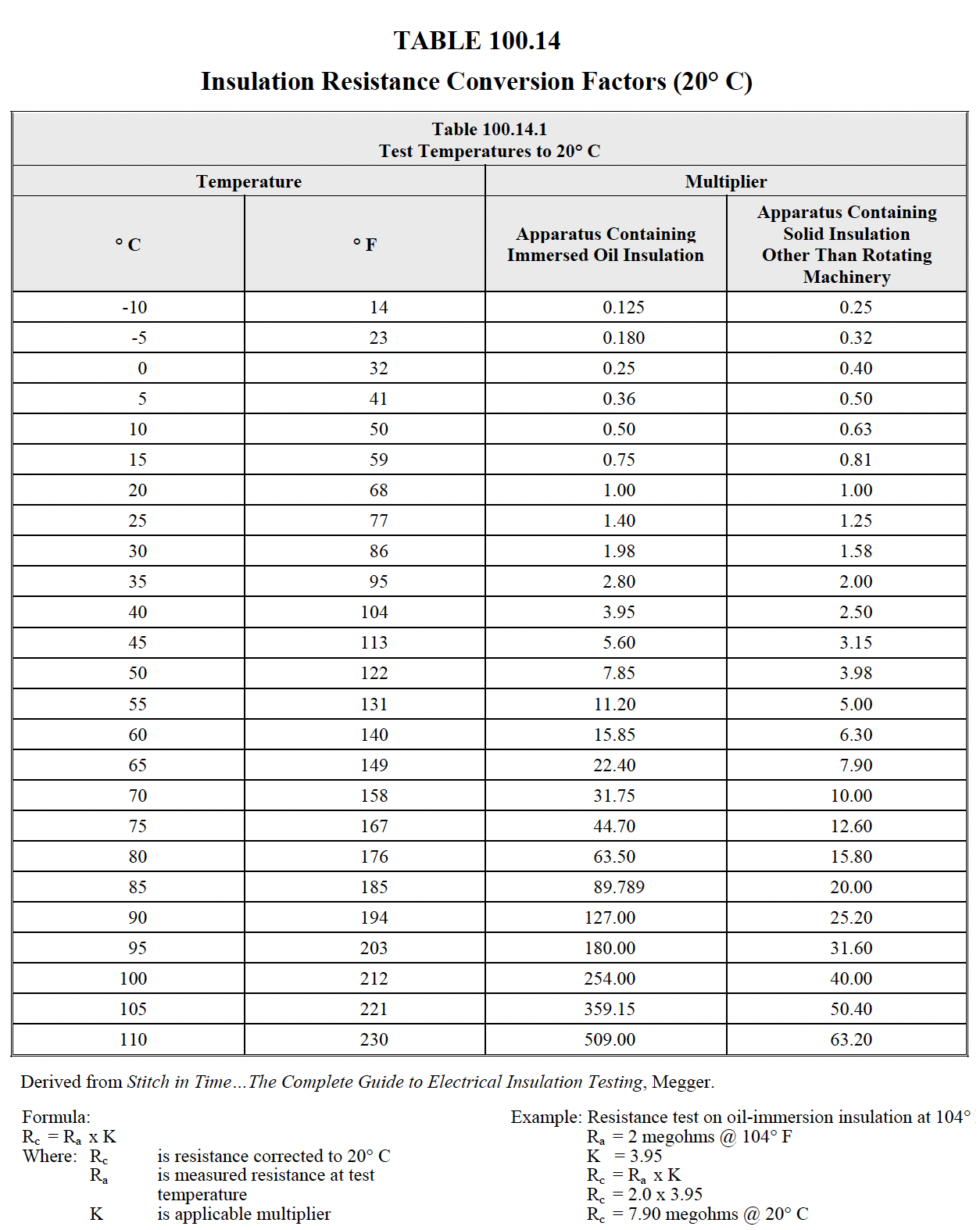
NETA ATS TABLE 100.14
Insulation Resistance Conversion Factors (20° C)
Neta Table 100.5
PURPOSE:

Lorem ipsum dolor sit amet consectetur adipisicing elit. Cumque officiis, dolores aut saepe mollitia enim ipsum! Fuga, doloribus cumque eveniet blanditiis sapiente consequatur, accusamus inventore iusto sed tempora est sit?

NETA Test Procedure

NETA ATS

7.13 Grounding Systems

A. Visual and Mechanical Inspection:
  1. Verify ground system is in compliance with drawings, specifications, and NFPA 70 National Electrical Code Article 250.
  2. Inspect physical and mechanical condition.
  3. Inspect bolted electrical connections for high resistance using one or more of the following methods:
    1. Use of low-resistance ohmmeter in accordance with Section 7.13.B.1.
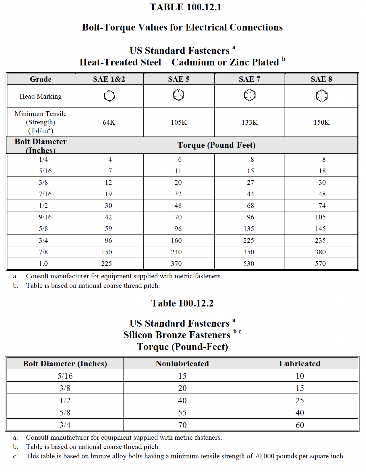
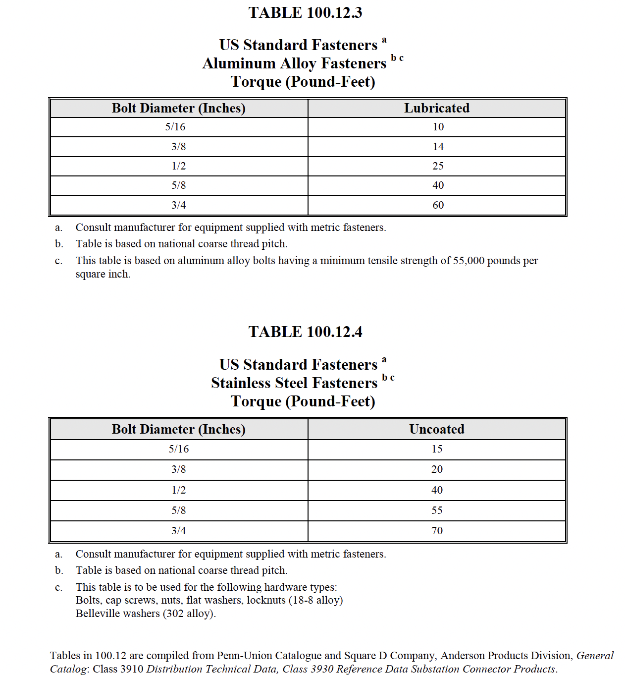
    2. Verify tightness of accessible bolted electrical connections by calibrated torquewrench method in accordance with manufacturer’s published data or Table 100.12.
  4. Inspect anchorage.
B. Electrical Tests:
  1. Perform resistance measurements through bolted connections with a low-resistance ohmmeter, if applicable, in accordance with section 7.13.A.13.1.
  2. Perform fall-of-potential or alternative test in accordance with ANSI/IEEE 81 on the main grounding electrode or system.
  3. Perform point-to-point tests to determine the resistance between the main grounding system and all major electrical equipment frames, system neutral, and derived neutral points.
  4. C. Test Values – Visual and Mechanical
C. Test Values – Visual and Mechanical
  1. Grounding system electrical and mechanical connections shall be free of corrosion. (7.13.A.2)
  2. Compare bolted connection resistance values to values of similar connections. Investigate values which deviate from those of similar bolted connections by more than 50 percent of the lowest value. (7.13.A.3.1)
  3. Bolt-torque levels shall be in accordance with manufacturer’s published data. In the absence of manufacturer’s published data, use Table 100.12. (7.13.A.3.2)
D. Test Values – Electrical
  1. Compare bolted connection resistance values to values of similar connections. Investigate values which deviate from those of similar bolted connections by more than 50 percent of the lowest value.
  2. The resistance between the main grounding electrode and ground shall be no greater than five ohms for large commercial or industrial systems and one ohm or less for generating or transmission station grounds unless otherwise specified by the owner. (Reference ANSI/IEEE Standard 142)
  3. Investigate point-to-point resistance values that exceed 0.5 ohm.

NETA MTS

7.13 Grounding Systems

A. Visual and Mechanical Inspection:
  1. Verify ground system is in compliance with drawings, specifications, and NFPA 70 National Electrical Code Article 250.
  2. Inspect physical and mechanical condition.
  3. Inspect bolted electrical connections for high resistance using one or more of the following methods:
    1. Use of low-resistance ohmmeter in accordance with Section 7.13.B.1.
    2. Verify tightness of accessible bolted electrical connections by calibrated torquewrench method in accordance with manufacturer’s published data or Table 100.12.
  4. Inspect anchorage.
B. Electrical Tests:
  1. Perform resistance measurements through bolted connections with a low-resistance ohmmeter, if applicable, in accordance with section 7.13.A.13.1.
  2. Perform fall-of-potential or alternative test in accordance with ANSI/IEEE 81 on the main grounding electrode or system.
  3. Perform point-to-point tests to determine the resistance between the main grounding system and all major electrical equipment frames, system neutral, and derived neutral points.
  4. C. Test Values – Visual and Mechanical
C. Test Values – Visual and Mechanical
  1. Grounding system electrical and mechanical connections shall be free of corrosion. (7.13.A.2)
  2. Compare bolted connection resistance values to values of similar connections. Investigate values which deviate from those of similar bolted connections by more than 50 percent of the lowest value. (7.13.A.3.1)
  3. Bolt-torque levels shall be in accordance with manufacturer’s published data. In the absence of manufacturer’s published data, use Table 100.12. (7.13.A.3.2)
D. Test Values – Electrical
  1. Compare bolted connection resistance values to values of similar connections. Investigate values which deviate from those of similar bolted connections by more than 50 percent of the lowest value.
  2. The resistance between the main grounding electrode and ground shall be no greater than five ohms for large commercial or industrial systems and one ohm or less for generating or transmission station grounds unless otherwise specified by the owner. (Reference ANSI/IEEE Standard 142)
  3. Investigate point-to-point resistance values that exceed 0.5 ohm.
NETA ATS / MTS
Neta Table 100.12
Neta Table 100.12