| High Voltage Transformers | |
|---|---|
Transformer types and Applications |
|
|
|
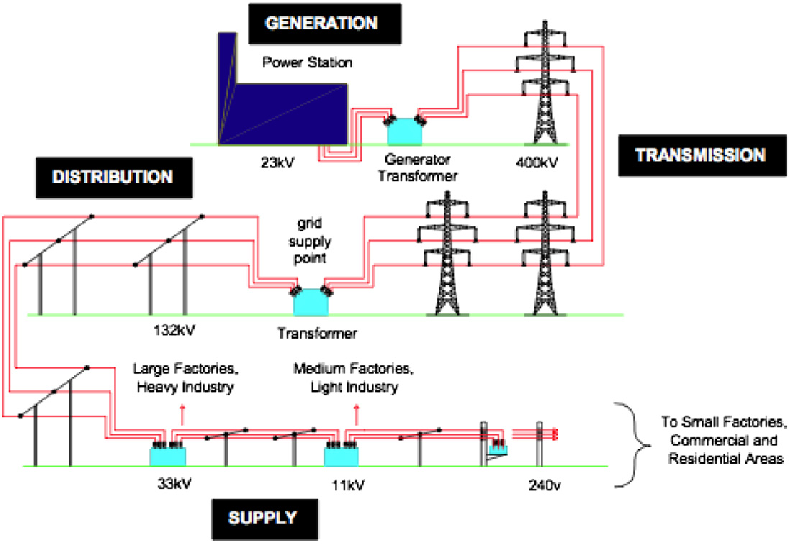
Long-term resistance to ageing A GSU transformer is loaded at 100 percent rating 24/7, throughout the year. It must be built to withstand the thermal load of high currents being fed into its windings from the generator without overheating, which would shorten its lifetime due to accelerated ageing. Standards organizations such as American National Standards Institute/Institute of Electrical and Electronic Engineers (ANSI/IEEE) consider average GSU transformer life to be 20 to 25 years. This estimate is based on continuous operation at rated load and service conditions with an average ambient temperature of 40 ºC (104 degrees Fahrenheit [ºF]) and a temperature rise of 65 ºC. This estimate is also based on the assumption that transformers receive adequate maintenance over their service life [26]. They are suitable for nuclear, thermal and hydraulic applications from small to high voltages with power ratings from 5 MVA to 1000 MVA. The step-up transformers have delta-connected LV windings energized by the generator voltage, while star connected HV windings are connected to the transmission lines. Large GSUs may be rated in hundreds of MVAs. A GSU transformer can cost well over a million dollars and take 18 months to 2 years or longer to obtain. Each one is designed for a specific application. If one fails, this may mean a unit or whole plant could be down for as long 2 years, costing multiple millions of dollars in lost generation, in addition to the replacement cost of the transformer itself. This is one reason that proper maintenance is critical. Transformers play an important role in our electrical generation transmission and distribution systems. Transformers make it possible to transmit large amounts of power over long distances. Transformer function is based on the principle that electrical energy is transferred efficiently by magnetic induction from one circuit to another. When one winding of a transformer is energized from an alternating current (AC) source, an alternating magnetic field is established in the transformer core. Alternating magnetic lines of force, called “flux,” circulate through the core. With a second winding around the same core, a voltage is induced by the alternating flux lines. A circuit, connected to the terminals of the second winding, results in current flow. 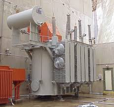
Medium Voltage Dry Type transformer. |
|
| Medium Voltage Transformers | ||
|---|---|---|
| Principal of Operation |
Transformer function is based on the principle that electrical energy is transferred efficiently by magnetic induction from one circuit to another. When one winding of a transformer is energized from an alternating current (AC) source, an alternating magnetic field is established in the transformer core. Alternating magnetic lines of force, called “flux,” circulate through the core. With a second winding around the same core, a voltage is induced by the alternating flux lines. A circuit, connected to the terminals of the second winding, results in current flow. |
|
| Three Phase Pad Mounted |
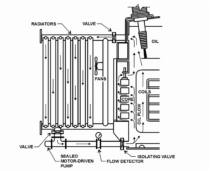
Three-phase, pad-mounted transformers,are best suited for commercial applications in public access areas and where underground service is required. Construction allows installation in locations accessible to the general public without the need for protective fencing or vaults. These units are ideally suited for apartment buildings, schools, hospitals, shopping centers, commercial buildings, or industrial sites Transformers smaller than 500 kVA are generally called distribution transformers. Pole-top and small, pad-mounted transformers that serve residences and small businesses are typically distribution transformers. Generator step-up transformers, used in Reclamation powerplants, receive electrical energy at generator voltage and increase it to a higher voltage for transmission lines. Conversely, a step-down transformer receives energy at a higher voltage and delivers it at a lower voltage for distribution to various loads. Power transformers are defined as transformers rated 500 kVA and larger. Larger transformers are oil-filled for insulation and cooling; a typical GSU transformer may contain several thousand gallons of oil. One must always be aware of the possibility of spills, leaks, fires, and environmental risks this oil poses. 

Continue reading
centrifugal treatment |
|
| Substation |
The substation transformer is the heart of the electrical substation. This transformer changes the relationship between the incoming voltage and current and the outgoing voltage and current. Substation transformers are rated by their primary and secondary voltage relationship and their power carrying capability. For example, a typical substation transformer would be rated 15 kV, 25 kV, 35 kV or 46 kV on the primary at a power rating of about 5-20 MVA. The secondary or low voltage can be 15 kV down to 5 kV or even less than 600 V. Substation-style transformer design and functionality is dictated by IEEE standards C57.12.00 and C57.12.36. These type transformers consist of a core and coils immersed in oil or dielectric fluid in a steel tank. The oil or fluid serves both as an insulator and as a coolant to keep the core at reliable operating temperatures. Substation units are easily identified by their exposed bushings, gauges, panels or monitoring equipment and are typically located behind a fence or with a restricted area. 
Continue reading
The substation transformer is the heart of the electrical substation. |
|
| Auto Transformers |
Continue reading
INFO |
|
| Overhead Transformers |
Single-phase pole-mounted transformers are frequently installed in residential areas but can also be common for small businesses requiring three-phase power from a bank. These transformers can vary in size from as small as 5 kVA to as large as 500 kVA, with voltages up to 35 kV line-to-line. Pole-mounted transformer banks allow three single phase units to be connected to a three-phase system to distribute through overhead lines. Winding connection styles, mounting standards, and overall layout and functionality is held to IEEE standard C57.12.20.
Continue reading
INFO |
|
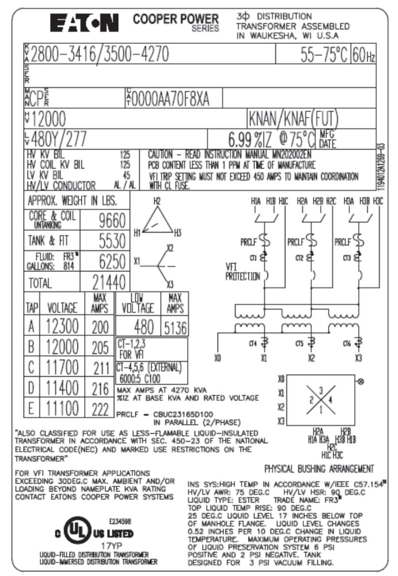
| Power Transformer Nameplate Data | ||||||||||||||||||||||||||||||||||||||||||||||||||||||||||||||||||||||||||||||||||||||||||||||||||||||||||||||||
|---|---|---|---|---|---|---|---|---|---|---|---|---|---|---|---|---|---|---|---|---|---|---|---|---|---|---|---|---|---|---|---|---|---|---|---|---|---|---|---|---|---|---|---|---|---|---|---|---|---|---|---|---|---|---|---|---|---|---|---|---|---|---|---|---|---|---|---|---|---|---|---|---|---|---|---|---|---|---|---|---|---|---|---|---|---|---|---|---|---|---|---|---|---|---|---|---|---|---|---|---|---|---|---|---|---|---|---|---|---|---|---|---|
|
||||||||||||||||||||||||||||||||||||||||||||||||||||||||||||||||||||||||||||||||||||||||||||||||||||||||||||||||
Manufactures:
Dry Type:"Dry-type" is a reference to the type of insulation medium, which means that the core and coil is cooled and insulated by air, as opposed to "liquid immersed" transformers that use oil as the coolant/insulant. 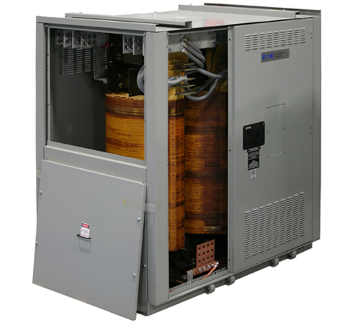
Medium Voltage Dry Type transformer. Dry Type:"Dry-type" is a reference to the type of insulation medium, which means that the core and coil is cooled and insulated by air, as opposed to "liquid immersed" transformers that use oil as the coolant/insulant. 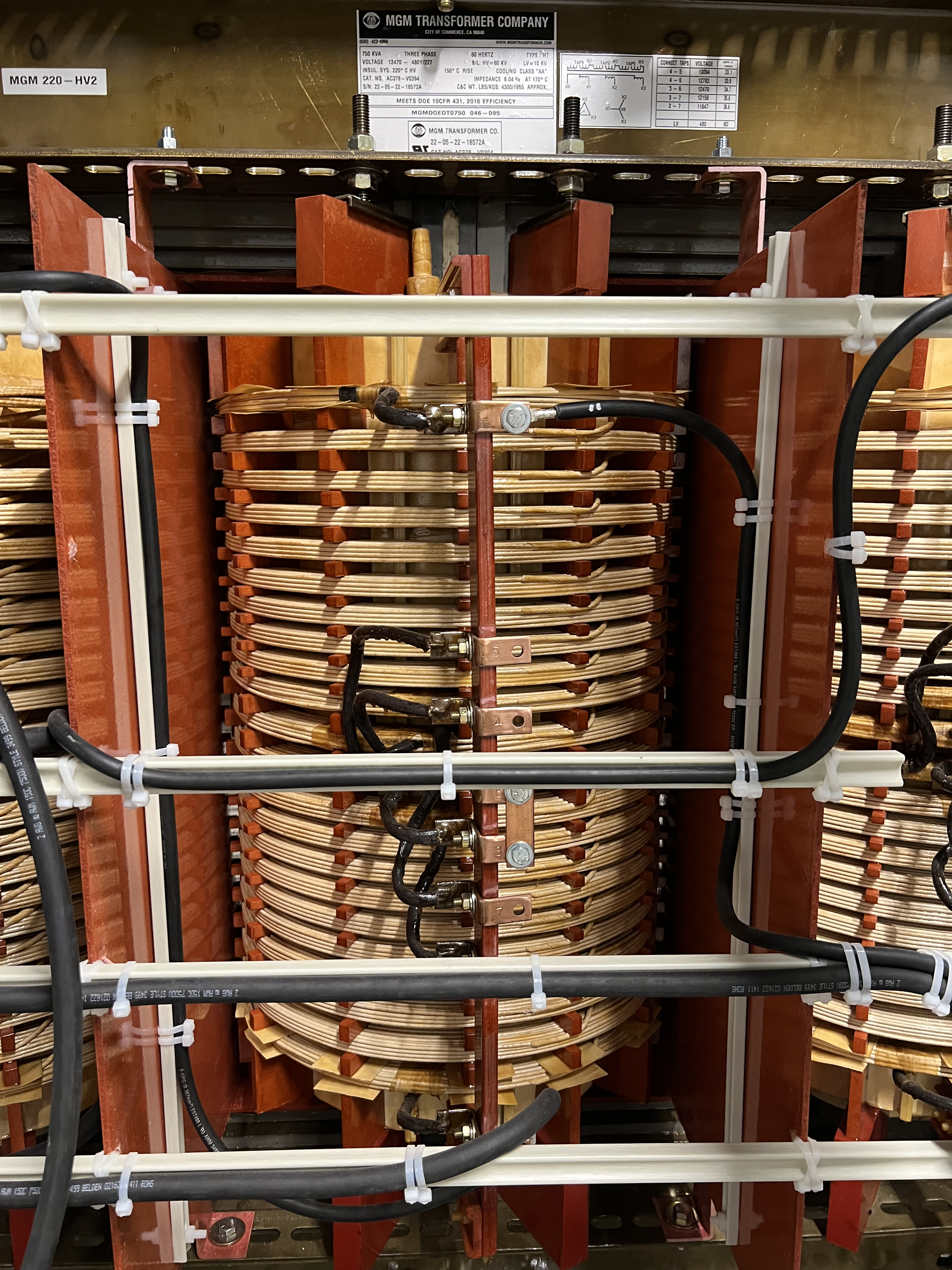
Medium Voltage Dry Type transformer. Oil Filled:Increasing the cooling rate of a transformer increases its capacity. Cooling methods must not only maintain a sufficiently low average temperature but must prevent an excessive temperature rise in any portion of the transformer (i.e., it must prevent hot spots). For this reason, working parts of large transformers are usually submerged in high-grade insulating oil. This oil must be kept as free as possible from moisture and oxygen, dissolved combustible gases, and particulates. 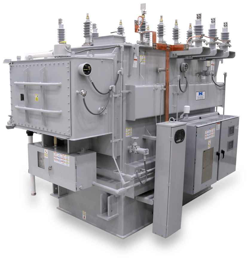
Medium Voltage Dry Type transformer Oil Filled:Increasing the cooling rate of a transformer increases its capacity. Cooling methods must not only maintain a sufficiently low average temperature but must prevent an excessive temperature rise in any portion of the transformer (i.e., it must prevent hot spots). For this reason, working parts of large transformers are usually submerged in high-grade insulating oil. This oil must be kept as free as possible from moisture and oxygen, dissolved combustible gases, and particulates. 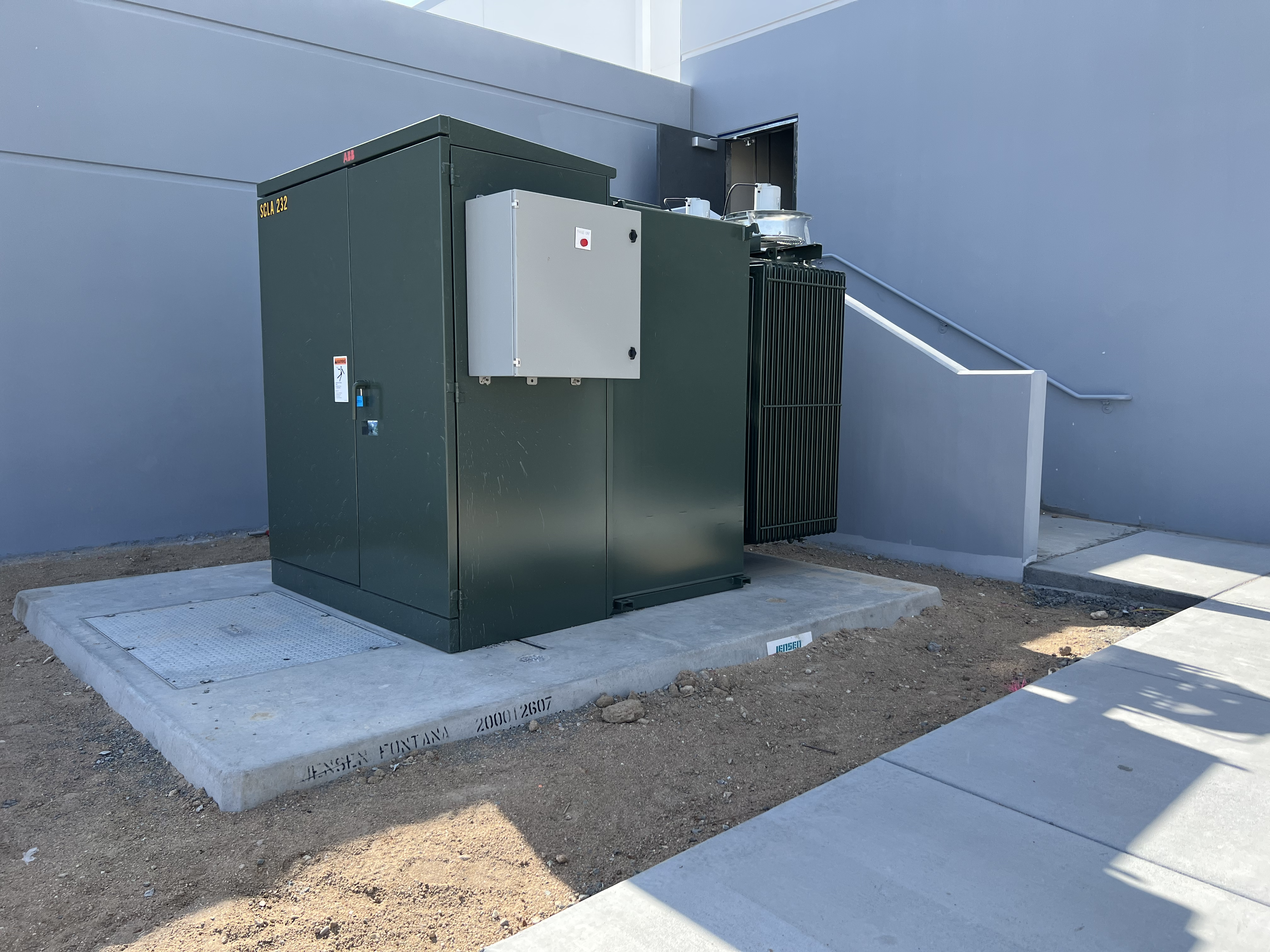
Medium Voltage Dry Type transformer CORE:
A simple transformer is composed of two coils wound around a soft iron core. The core creates a path for magnetic lines of flux, coupling the magnetic flux produced by the primary source winding, to the secondary load windings. Magnetic field coupling, also called inductive coupling, occurs when energy is coupled from one circuit to another through a magnetic field. The primary winding currents are the sources of magnetic fields, producing lines of flux, which induce voltage and current in the secondary winding. The voltage and current induced in secondary winding coil produces the output current and voltage of the transformer. Thus, the load is connected to it. 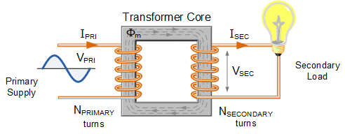
Basic Transformer Model 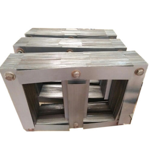
Magnetic Core 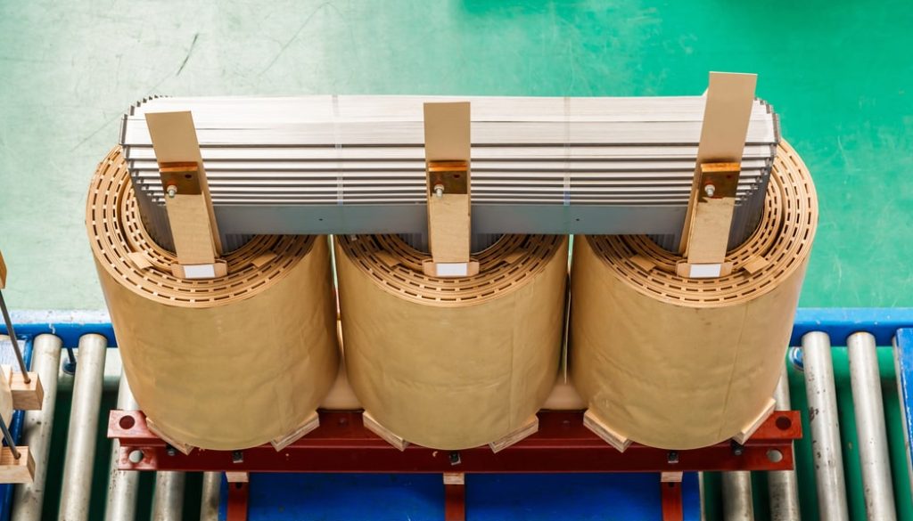
Magnetic Core Turns Ratio:
This is the ratio of the number of turns in the primary winding to the number of turns in the secondary winding. The voltage times the amperage on the primary winding is equal to the voltage times the amperage on the secondary winding. The ratio between the primary voltage and the secondary voltage is the same as the ratio between the number of turns on the primary windings and the number of turns on the secondary winding. The current ratio is the inverse of the turns ration. Thus, by knowing the turns ratio and the volt-amps of one winding, the volt-amps of the other winding can be determined. Knowing the amount of current that runs through each is important when planning a new service installation, troubleshooting, or balancing loads \( Turns Ratio = \frac{ N_{1}}{N_{2}} = \frac{ V_{1}}{V_{2}} = \frac{ I_{2}}{I_{1}} \) 
Basic Transformer Model
A transformer rated for 2,400 volts on its primary side, and 240 volts on its secondary side has a turns ratio of 10:1. The implication here is that a transformer with a 10:1 turns ratio could have 2,400 turns on the primary and 240 turns on the secondary, or 8,000 turns on the primary and 800 turns on the secondary, etc. KVA:
kVA is used to express a transformer rating because not all transformer loads are purely resistive. The resistive component consumes power that is measured in watts, whereas the reactive component consumes power measured in VARs. The vector sum of these two loads is the total load, VA or kVA Capacity (or rating) of a transformer is limited by the temperature that the insulation can tolerate. Ratings can be increased by reducing core and copper losses, by increasing the rate of heat dissipation (better cooling), or by improving transformer insulation so it will withstand higher temperatures. 
Medium Voltage Dry Type transformer. Voltage:Voltage & Current RelationshipThe total induced voltage in each winding is proportional to the number of turns in that winding. If E1 is the primary voltage and I1 the primary current, E2 the secondary voltage and I2 the secondary current, N1 the primary turns and N2 the secondary turns, then: \( \frac{ E_{1}}{E_{2}} = \frac{ N_{1}}{N_{2}} = \frac{ I_{2}}{I_{1}} \) 
Medium Voltage Dry Type transformer. Current:Single Phase Current\(I_{FLA}=\frac{KVA \cdot 1000}{V_{Phase}} \) Three Phase Current\(I_{FLA}=\frac{KVA \cdot 1000}{\sqrt{3}\cdot V_{Phase}} \) Polarity
Polarity is the relative direction of induced voltages between the high-voltage terminals and the low-voltage terminals. With standard markings, the voltage from H1 to H2 is always in the same direction or in phase with the voltage from X1 to X2. Polarity is a property of single-phase transformers having to do with the identification and location of terminals. For individual use of single-phase transformers, polarity is unimportant, but for parallel connection or connection in a three-phase bank, polarity is very important Polarity is the relative direction of induced voltages between the high-voltage terminals and the low-voltage terminals. With standard markings, the voltage from H1 to H2 is always in the same direction or in phase with the voltage from X1 to X2. Because a 60-cycle sine wave (AC) reverses its direction 120 times a second, it is hard to determine the direction at any particular time. In designating polarity, we pick an instant, any instant, and assume the current is flowing in one direction. Polarity is the relative instantaneous direction of current in the leads of a transformer. At a given instant, the primary and secondary leads have the same polarity when the current enters the primary lead and leaves the secondary lead in the same direction as through the two leads form a continuous circuit. 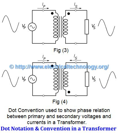
Medium Voltage Dry Type transformer. 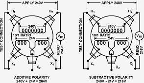
Medium Voltage Dry Type transformer. Frequency:
European power is typically 50Hz while North American power is usually 60hz.
Transformers cannot change the frequency of the source kva (voltage & current). If the source frequency is 60 Hz, the output will also be 60 Hz. In most parts of the Americas, it is typically 60Hz, and in the rest of the world it is typically 50Hz. Places that use the 50 Hz frequency tend to use 230 V RMS, and those that use 60Hz tend to use 117 V RMS. *** 
Medium Voltage Dry Type transformer Impedance:What is Meant by "Impedance" in Transformers?Impedance is the current limiting characteristic of a transformer and is expressed in percentage.
The percentage impedance of a transformer (Z%) is the
voltage drop on full load due to the winding resistance
and leakage reactance expressed as a percentage of the
rated voltage.
In general, impedance has a complex value, which means
that loads generally have a resistance to the source
that is in phase with a sinusoidal source signal and
reactance that is
out of phase with a sinusoidal source signal. Why is Impedance Important?It is used for determining the interrupting capacity of a circuit breaker or fuse employed to protect the primary of a transformer. Example: Determine a minimum circuit breaker trip rating and nterrupting capacity for a 10 KVA single phase transformer with 4% impedance, to be operated from a 480 volt 50 Hz source. Maximum Short Circuit Secondary CurrentThe maximum short circuit current that can be obtained from the output of the transformer is limited by the impedance of the transformer and is determined by multiplying the reciprocal of the impedance times the full load current.
*** 
Medium Voltage Dry Type transformer Transformer Construction:
Transformer tanks are ruggedly made of high quality steel. Welds are leak-proof and bolted covers are equipped with gaskets. The tank provides the means to hold the core and windings in an oil bath so that the insulation and the cooling properties of the materials used in the construction of the core and windings are optimized. Oil that is outside of the transformer on the tank or on the ground indicates a problem that the Substation Operator should investigate. 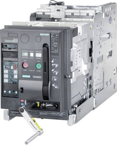
Free Breathing:
Transformer tanks are ruggedly made of high quality steel. Welds are leak-proof and bolted covers are equipped with gaskets. The tank provides the means to hold the core and windings in an oil bath so that the insulation and the cooling properties of the materials used in the construction of the core and windings are optimized. Oil that is outside of the transformer on the tank or on the ground indicates a problem that the Substation Operator should investigate. 
Sealed:
Transformer tanks are ruggedly made of high quality steel. Welds are leak-proof and bolted covers are equipped with gaskets. The tank provides the means to hold the core and windings in an oil bath so that the insulation and the cooling properties of the materials used in the construction of the core and windings are optimized. Oil that is outside of the transformer on the tank or on the ground indicates a problem that the Substation Operator should investigate. 
Breathing Regulator:
Transformer tanks are ruggedly made of high quality steel. Welds are leak-proof and bolted covers are equipped with gaskets. The tank provides the means to hold the core and windings in an oil bath so that the insulation and the cooling properties of the materials used in the construction of the core and windings are optimized. Oil that is outside of the transformer on the tank or on the ground indicates a problem that the Substation Operator should investigate. 
Cloride Regulator :
Transformer tanks are ruggedly made of high quality steel. Welds are leak-proof and bolted covers are equipped with gaskets. The tank provides the means to hold the core and windings in an oil bath so that the insulation and the cooling properties of the materials used in the construction of the core and windings are optimized. Oil that is outside of the transformer on the tank or on the ground indicates a problem that the Substation Operator should investigate. 
Breathing Regulator:
Transformer tanks are ruggedly made of high quality steel. Welds are leak-proof and bolted covers are equipped with gaskets. The tank provides the means to hold the core and windings in an oil bath so that the insulation and the cooling properties of the materials used in the construction of the core and windings are optimized. Oil that is outside of the transformer on the tank or on the ground indicates a problem that the Substation Operator should investigate. 
Expansion Tank:
Transformer tanks are ruggedly made of high quality steel. Welds are leak-proof and bolted covers are equipped with gaskets. The tank provides the means to hold the core and windings in an oil bath so that the insulation and the cooling properties of the materials used in the construction of the core and windings are optimized. Oil that is outside of the transformer on the tank or on the ground indicates a problem that the Substation Operator should investigate. 
Gas Seealed (Nitrogen):
Transformer tanks are ruggedly made of high quality steel. Welds are leak-proof and bolted covers are equipped with gaskets. The tank provides the means to hold the core and windings in an oil bath so that the insulation and the cooling properties of the materials used in the construction of the core and windings are optimized. Oil that is outside of the transformer on the tank or on the ground indicates a problem that the Substation Operator should investigate. 
Winding Insulation:Transformer windings are made of aluminum or copper. The windings are insulated by:
Insulating oils, fluids in liquid-filled transformers performs two functions: Insulating oils, fluids in liquid-filled transformers performs two functions:
It penetrates all parts of the winding insulation and replacing the weaker air insulation. Cooling Medium which remove the heat, generated in the windings and in the core, to the tank wall where it can be dissipated to the surrounding air The core loss and the copper loss in the transformer are converted to heat. Unless some means is provided for continuously removing the heat from the core and windings, they would get progressively hotter and eventually result in the failure of the transformer from overheating. In the oil filled transformer the oil is used, in addition to its insulating qualities, as a medium for carrying heat in the core and coils to the tank wall. The tank wall then dissipates this _hear to the surrounding air and maintains a heat balance. 
Insulating Fluids:Insulating oils, fluids in liquid-filled transformers performs two functions: Insulating oils, fluids in liquid-filled transformers performs two functions:
It penetrates all parts of the winding insulation and replacing the weaker air insulation. Cooling Medium which remove the heat, generated in the windings and in the core, to the tank wall where it can be dissipated to the surrounding air The core loss and the copper loss in the transformer are converted to heat. Unless some means is provided for continuously removing the heat from the core and windings, they would get progressively hotter and eventually result in the failure of the transformer from overheating. In the oil filled transformer the oil is used, in addition to its insulating qualities, as a medium for carrying heat in the core and coils to the tank wall. The tank wall then dissipates this _hear to the surrounding air and maintains a heat balance. 
Mineral Oil:
It has been used as the dielectric fluid for several generations of transformers. It has a longstanding record of good performance and low costs. It is considered a top choice for transformers for outdoor installations. It has very good dielectric and thermal performance. In fact, most of the norms for liquid filled transformers have been based on mineral oil. However, mineral oil is considered to be a flammable liquid and therefore, suffers from certain restrictions on its use and containment

Silicone:For several decades this was the preferred fluid when a “lessflammable” liquid was required. It has a relatively high fire point and is generally self extinguishing when the source of ignition is removed. Silicone has been used for many years in indoor applications, generally in vaulted areas. However, at high temperatures silicone can produce some chemicals which can be a health hazard. Also, it is the most expensive insulating fluid Beta:It is a blend of petrochemical oils and is 100% hydrocarbon. It has a fire point which is higher than mineral oil, thus qualifying as “less-flammable” liquid. However, its fire point is lower than either silicone or Envirotemp (FR3). Also, it is more expensive than mineral oil. 
FR3:It is a soy-based natural ester dielectric fluid which meets the requirements of “less-flammable” liquid. It is bio-degradable and is environment friendly. Cooper Power system claims that FR3 can extend the insulation life by drawing out moisture from paper insulation. The heat transfer properties are inferior to that of mineral oil and transformers have to be suitably designed for that, adding to cost. Also, certain precautions are needed during manufacture when using this liquid. It is much costlier than mineral oil and makes the initial cost of the transformer higher. The inherent dissipation factor of FR3 is higher than mineral oil and as a result the power factor of the whole transformer with FR3 is higher than one with mineral oil. The existing norms for acceptance for power factor of a new transformer are based on mineral oil and cannot be met with FR3. This fluid is still more expensive than Beta Fluid. 
Voltage taps allow an operator to change the wiring configuration of a transformer winding. Physically they are either a bolted connection between different winding positions or a switch; each switch position corresponds too a different winding configuration and voltage.
Most power transformers have taps on either primary or secondary windings to vary the number of turns and, thus, the output voltage. The percentage of voltage change, above or below normal, between different tap positions varies in different transformers. 
Medium Voltage Dry Type transformer.
Voltage supplied to a Transformer may vary from nominal voltage due to the distance from the substation or source. Higher or lower input voltage will result in higher or lower output voltage if there are no voltage adjustment taps present. In order to compensate for this voltage difference, transformers secondary voltage can be adjusted to nominal levels by adjusting the transformer's primary winding's voltage Tap. Transformer voltage taps change the voltage ratio of a transformer so that its secondary voltage stays at nominal. On large power transformers, taps on the primary are used to offset any higher or lower input voltages. These tap connections are usually set at the factory for nominal line voltage. If the voltage at the site is different, the taps are changed accordingly. Changing Voltage TapsStandard tap arrangements are at two and one-half and five percent of the rated primary voltage for both high and low voltage conditions. For example, if the transformer has a 480 volt primary and the available line voltage is running at 504 volts, the primary should be connected to the 5% tap above normal in order that the secondary voltage be maintained at the proper rating. The standard ASA and NEMA designation for taps are "ANFC" (above normal full capacity) and "BNFC" (below normal full capacity). 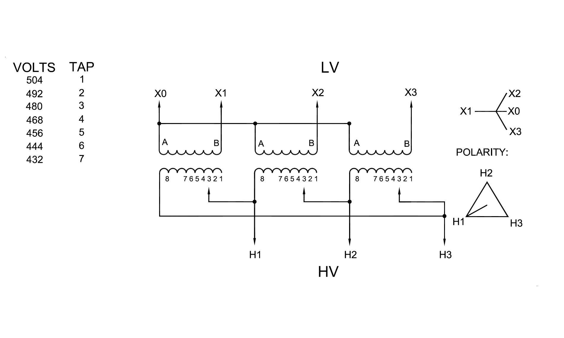
No Load Tap Changer:Tap changers on power transformers are either load tap changers or no-load tap changers. They may be installed in either or both the high or low side windings. The load tap changer permits the changing of taps while the transformer continues to carry load. The no-load tap changer requires the transformer be removed from service to permit the tap to be changed. Most no-load tap changers are installed on the high side winding and their movement has an inverse effect on the low side voltage. When the high side tap is ra winding. All three phases of the transformer change at the same time. However, each phase can be operated independently either electrically or manually. Lights or a calibrated dial are installed on each phase to show the tap position. 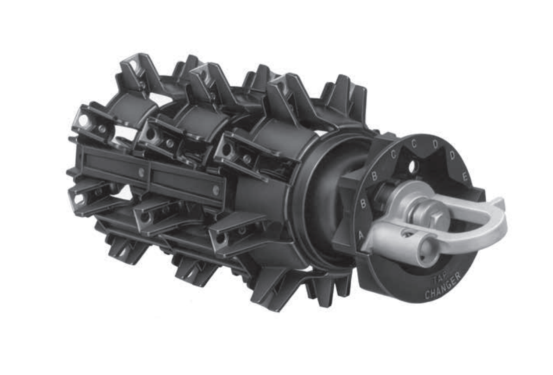
LTC:Tap changers on power transformers are either load tap changers or no-load tap changers. They may be installed in either or both the high or low side windings. The load tap changer permits the changing of taps while the transformer continues to carry load. The no-load tap changer requires the transformer be removed from service to permit the tap to be changed. Most no-load tap changers are installed on the high side winding and their movement has an inverse effect on the low side voltage. When the high side tap is ra winding. All three phases of the transformer change at the same time. However, each phase can be operated independently either electrically or manually. Lights or a calibrated dial are installed on each phase to show the tap position. 
TANK:
Transformer tanks are ruggedly made of high quality steel. Welds are leak-proof and bolted covers are equipped with gaskets. The tank provides the means to hold the core and windings in an oil bath so that the insulation and the cooling properties of the materials used in the construction of the core and windings are optimized. Oil that is outside of the transformer on the tank or on the ground indicates a problem that the Substation Operator should investigate. 
Free Breathing:
This type is open to the atmosphere (i.e., the airspace above the liquid is at atmospheric pressure). The transformer breathes as the air pressure and temperature change outside the tank. Some of these transformers can be equipped with dehydrating compounds in the breather. 
Sealed:
These transformers are equipped with an inert gas, such as nitrogen that is under pressure above the liquid in the transformer tank. Generally, the pressure range for this type of transformer is −8 to +8 lb/in.2 
Breathing Regulator:
Transformer tanks are ruggedly made of high quality steel. Welds are leak-proof and bolted covers are equipped with gaskets. The tank provides the means to hold the core and windings in an oil bath so that the insulation and the cooling properties of the materials used in the construction of the core and windings are optimized. Oil that is outside of the transformer on the tank or on the ground indicates a problem that the Substation Operator should investigate. 
Cloride Regulator :
Transformer tanks are ruggedly made of high quality steel. Welds are leak-proof and bolted covers are equipped with gaskets. The tank provides the means to hold the core and windings in an oil bath so that the insulation and the cooling properties of the materials used in the construction of the core and windings are optimized. Oil that is outside of the transformer on the tank or on the ground indicates a problem that the Substation Operator should investigate. 
Breathing Regulator:
Transformer tanks are ruggedly made of high quality steel. Welds are leak-proof and bolted covers are equipped with gaskets. The tank provides the means to hold the core and windings in an oil bath so that the insulation and the cooling properties of the materials used in the construction of the core and windings are optimized. Oil that is outside of the transformer on the tank or on the ground indicates a problem that the Substation Operator should investigate. 
Expansion Tank:
Transformer tanks are ruggedly made of high quality steel. Welds are leak-proof and bolted covers are equipped with gaskets. The tank provides the means to hold the core and windings in an oil bath so that the insulation and the cooling properties of the materials used in the construction of the core and windings are optimized. Oil that is outside of the transformer on the tank or on the ground indicates a problem that the Substation Operator should investigate. 
Gas Seealed (Nitrogen):
Transformer tanks are ruggedly made of high quality steel. Welds are leak-proof and bolted covers are equipped with gaskets. The tank provides the means to hold the core and windings in an oil bath so that the insulation and the cooling properties of the materials used in the construction of the core and windings are optimized. Oil that is outside of the transformer on the tank or on the ground indicates a problem that the Substation Operator should investigate. 
Temperature Rise:Transformer temperature rise is defined as the average temperature rise of the windings above the ambient (surrounding) temperature, when the transformer is loaded at its nameplate rating. Liquid-filled transformers come in the following standard rises:
These values are based on a maximum ambient temperature of 40C. That means, for example, that an 80C rise dry transformer will operate at an average winding temperature of 120C when at full-rated load, in a 40C ambient environment. What is BIL and How Does it Apply to Transformers ListedBIL is an abbreviation for Basic Impulse Level. Impulse tests are dielectric tests that consist of the application of a high frequency steep wave front voltage between windings, and between windings and ground. The Basic Impulse Level of a transformer is a method of expressing the voltage surge (lightning, switching surges, etc.) that a transformer will tolerate without breakdown. All transformers manufactured in this catalog, 600 volts and below, will withstand the NEMA standard BIL rating, which is 10 KV. This assures the user that he will not experience breakdowns when his system is properly protected with lightning arrestors or similar surge protection devices. Basic impulse insulation level (BIL): BIL is the crest value of the impulse voltage that the transformer is required to withstand without failure. The transformer BIL impulse duration is 1.2 50 μs. That is, the impulse reaches its peak value in 1.2 μs and then decays to 50% of its peak value in 50 μs. In addition to full BIL value, transformers are tested for chopped-wave withstand (115% of BIL) and front-of-the-wave withstand (160% of BIL). These tests are intended to simulate conditions that can occur when transformers are subjected to lightning surges.
:
kVA is used to express a transformer rating because not all transformer loads are purely resistive. The resistive component consumes power that is measured in watts, whereas the reactive component consumes power measured in VARs. The vector sum of these two loads is the total load, VA or kVA Capacity (or rating) of a transformer is limited by the temperature that the insulation can tolerate. Ratings can be increased by reducing core and copper losses, by increasing the rate of heat dissipation (better cooling), or by improving transformer insulation so it will withstand higher temperatures. 
Voltage:The voltage designation defines both the way a transformer may be applied to a system and the transformer design. IEEE Std C57.12.00 defines the designation of voltage ratings of single and three-phase transformers. 
Voltage & Current RelationshipThe total induced voltage in each winding is proportional to the number of turns in that winding. If E1 is the primary voltage and I1 the primary current, E2 the secondary voltage and I2 the secondary current, N1 the primary turns and N2 the secondary turns, then: \( \frac{ E_{1}}{E_{2}} = \frac{ N_{1}}{N_{2}} = \frac{ I_{2}}{I_{1}} \) Where:Voltage:The voltage designation defines both the way a transformer may be applied to a system and the transformer design. IEEE Std C57.12.00 defines the designation of voltage ratings of single and three-phase transformers. 
Voltage & Current RelationshipThe total induced voltage in each winding is proportional to the number of turns in that winding. If E1 is the primary voltage and I1 the primary current, E2 the secondary voltage and I2 the secondary current, N1 the primary turns and N2 the secondary turns, then: \( \frac{ E_{1}}{E_{2}} = \frac{ N_{1}}{N_{2}} = \frac{ I_{2}}{I_{1}} \) Where:Voltage:The voltage designation defines both the way a transformer may be applied to a system and the transformer design. IEEE Std C57.12.00 defines the designation of voltage ratings of single and three-phase transformers. 
Voltage & Current RelationshipThe total induced voltage in each winding is proportional to the number of turns in that winding. If E1 is the primary voltage and I1 the primary current, E2 the secondary voltage and I2 the secondary current, N1 the primary turns and N2 the secondary turns, then: \( \frac{ E_{1}}{E_{2}} = \frac{ N_{1}}{N_{2}} = \frac{ I_{2}}{I_{1}} \) Where: |
||||||||||||||||||||||||||||||||||||||||||||||||||||||||||||||||||||||||||||||||||||||||||||||||||||||||||||||||
| Transformer Test Procedures | |
|---|---|
| Dry Type, Low Voltage 600 volts or Greater | |
Transformers do not require as much attention as most other equipment; however, the care and maintenance they do require is absolutely critical. Because of their reliability, maintenance is sometimes ignored, causing reduced service life and, at times, outright failure. |
|
| NETA Test Procedure | |
|---|---|
NETA ATS7.2.2 Transformers, Liquid-FilledA. Visual and Mechanical Inspection:
B. Electrical Tests:
C. Test Values – Visual and Mechanical
D. Test Values – Electrical
NETA ATS7.2.1.2 Transformers, Dry Type, Air-Cooled, LargeA. Visual and Mechanical Inspection:
B. Electrical Tests:
C. Test Values – Visual and Mechanical
D. Test Values – Electrical
NETA MTS7.2.1.1 Transformers, Dry Type, Air-Cooled, Low-Voltage, SmallA. Visual and Mechanical Inspection:
B. Electrical Tests:
C. Test Values – Visual and Mechanical
D. Test Values – Electrical
NETA MTS7.2.1.2 Transformers, Dry Type, Air-Cooled, LargeA. Visual and Mechanical Inspection:
B. Electrical Tests:
C. Test Values – Visual and Mechanical
D. Test Values – Electrical
NETA ATS / MTS
TABLE 100.5
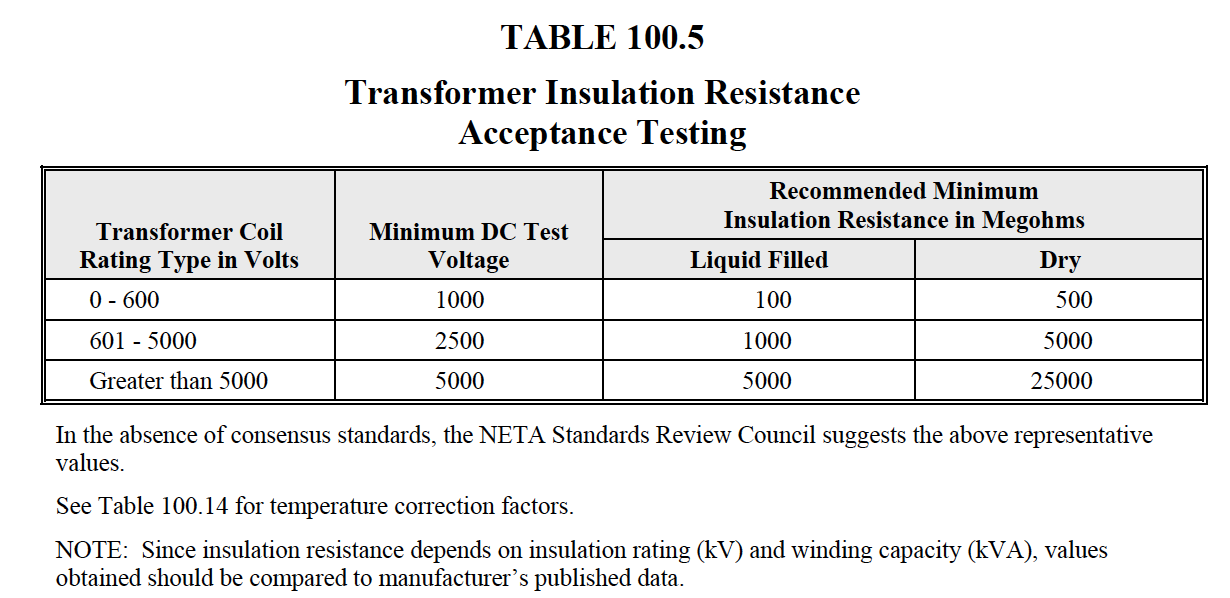
NETA ATS / MTS
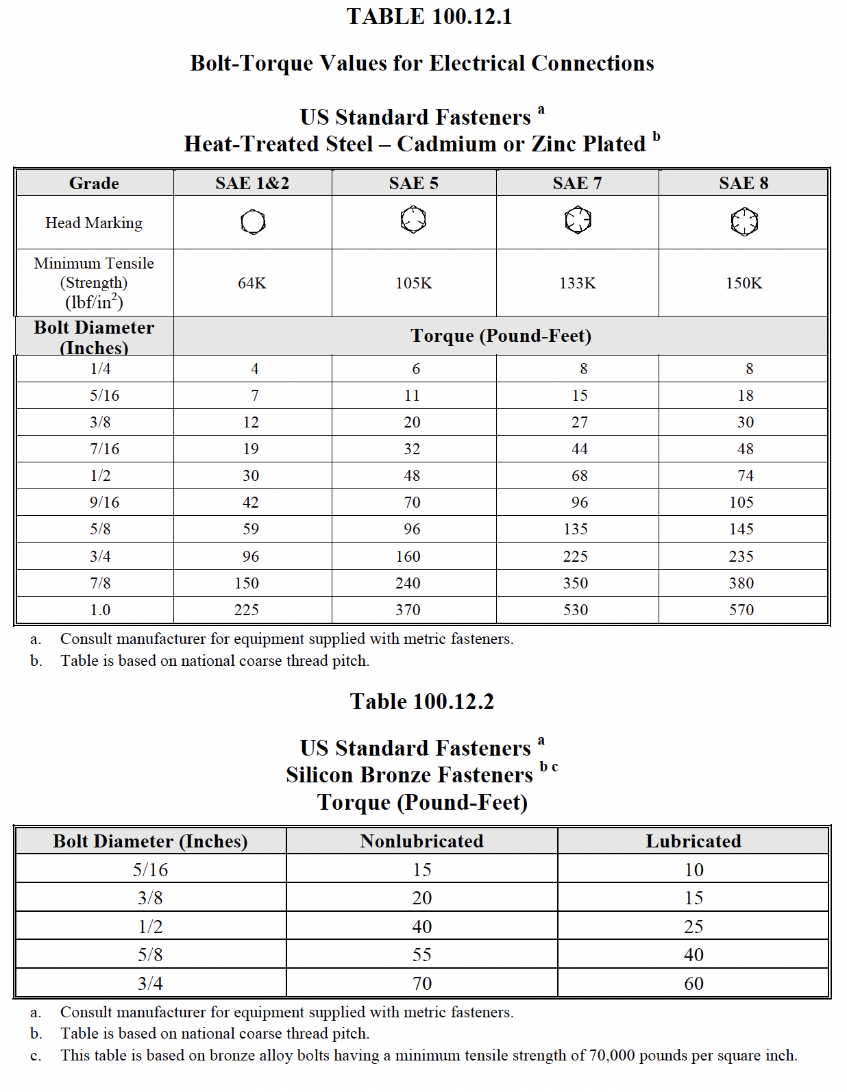
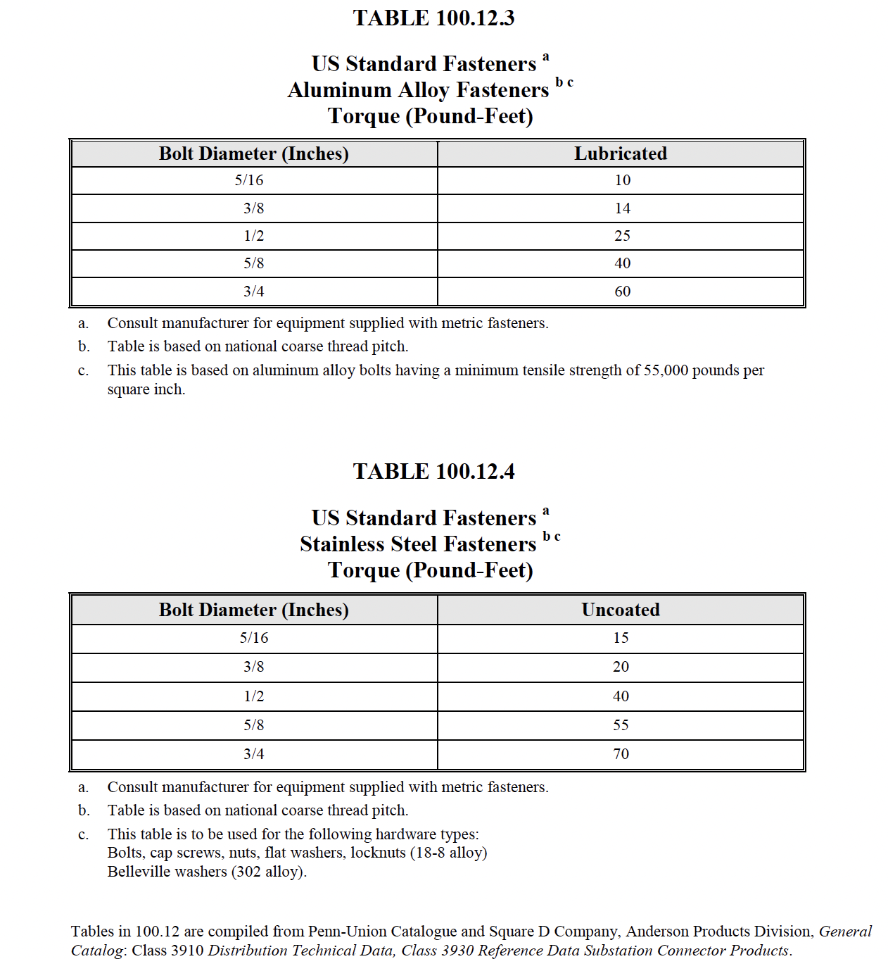
NETA ATS / MTS
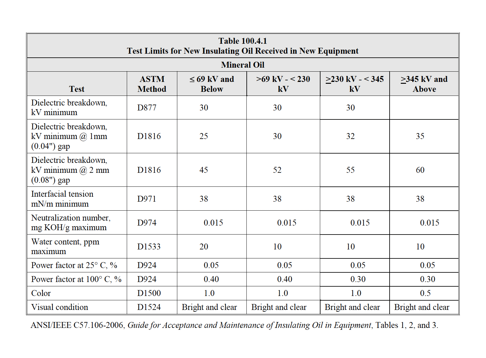
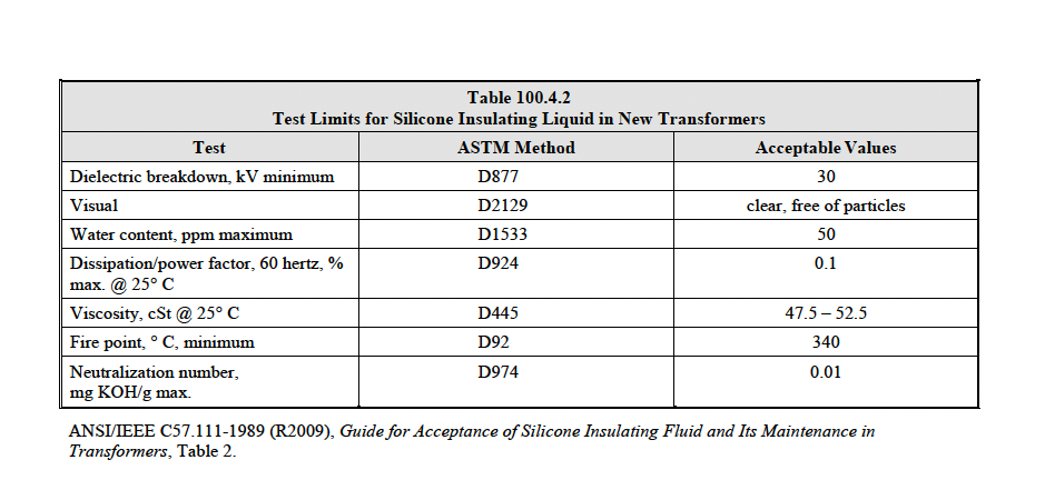
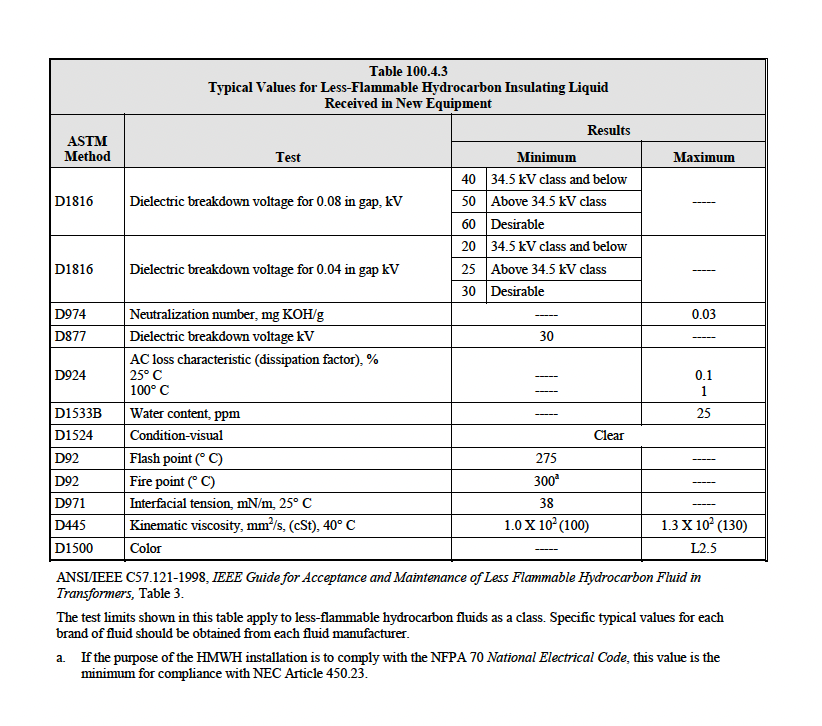
|
|
| Mineral Oil | |
|---|---|
| Low Info | |
| Moisture |
The ability of insulating oils, fluids, and gases to serve as effective dielectric and coolant is adversely affected by their deterioration. The deterioration of insulating oil, fluids, and gases is due to contamination, overheating, electrical stress, and oxidation. Moisture is the most common contaminant which adversely affects the insulating properties of these liquids and gases. High temperatures from increased load and/or environmental conditions accelerate the deterioration process. To assure service, safety, and maintenance, a condition monitoring program, consisting of electrical and chemical testing, is necessary for these dielectrics. |
| Moisture |
Moisture contamination is the most common cause of deterioration in the insulating quality of oil. Water can be present in oil in a dissolved form, as tiny droplets mixed with the oil (emulsion), or in a free state at the bottom of the container holding the oil.
Continue reading
Demulsifi cation occurs when the tiny droplets unite to form larger drops, which sink to the bottom and form a pool of free water. Water in the free state may be readily removed by fi ltering or centrifugal treatment. However, dissolved water is not removed by centrifugal treatment |
| Oxidation |
Atmospheric oxygen and oxygen contained in water are the sources available for the oxidation of insulating oils. When water is present in insulating oils, oxidation of the oil will take place |
| Transformer Types | |
|---|---|
| Low Voltage, Greater than 600V | |
| Askerels |
There has been a great increase in the use of less flammable liquids as an insulating and cooling medium in transformers. As these liquids are chemically different from mineral oils, they cannot be substituted in equipment designed for the use of mineral-oil type liquid. The NEC has officially designated these synthetic liquids as less flammable. There has been a great increase in the use of less flammable |
| Askerels |
Moisture contamination is the most common cause of deterioration in the insulating quality of oil. Water can be present in oil in a dissolved form, as tiny droplets mixed with the oil (emulsion), or in a free state at the bottom of the container holding the oil.
Continue reading
Demulsifi cation occurs when the tiny droplets |
| Silicone |
Atmospheric oxygen and oxygen contained in water are the sources available for the oxidation of insulating oils. When water is present in insulating oils, oxidation of the oil will take place |
| RTemp |
Atmospheric oxygen and oxygen contained in water are the sources available for the oxidation of insulating oils. When water is present in insulating oils, oxidation of the oil will take place |
| Wecosol R113 |
Atmospheric oxygen and oxygen contained in water are the sources available for the oxidation of insulating oils. When water is present in insulating oils, oxidation of the oil will take place |
| envirotemp (FR-3) |
Atmospheric oxygen and oxygen contained in water are the sources available for the oxidation of insulating oils. When water is present in insulating oils, oxidation of the oil will take place |
| Oil Sample Test | |||||||||||||||||||||||||||||||||||||||||||||||||||||||||||||||||||||||||||||||||||||||||||||||||||||
|---|---|---|---|---|---|---|---|---|---|---|---|---|---|---|---|---|---|---|---|---|---|---|---|---|---|---|---|---|---|---|---|---|---|---|---|---|---|---|---|---|---|---|---|---|---|---|---|---|---|---|---|---|---|---|---|---|---|---|---|---|---|---|---|---|---|---|---|---|---|---|---|---|---|---|---|---|---|---|---|---|---|---|---|---|---|---|---|---|---|---|---|---|---|---|---|---|---|---|---|---|---|
Dielectric Breakdown Voltage:
|
|||||||||||||||||||||||||||||||||||||||||||||||||||||||||||||||||||||||||||||||||||||||||||||||||||||
| Fluid | Range | Result |
|---|---|---|
| Mineral Oil | Less Than 23KV |
Satisfactory
|
| Greater Than 23KV |
Needs Reconditioning
|
Acid Neutralization Number:
ANSI/ASTM D 974
The acid number of the neutralization number is the milligrams (mg) of potassium hydroxide (KOH) required to neutralize the acid contained in 1 g of transformer liquid. Test data indicate that the acidity is proportional to the amount of oxygen absorbed by the liquid.
The acidity test measures the content of acids formed by oxidation. The acids are directly responsible for sludge formation. These acids precipitate out, as their concentration increases, and become sludge. They also react with metals to form another form of sludge in the transformer. The ASTM D974 and D664 are laboratory tests whereas D1534 is a field test which determines the approximate total acid value of the oil.
ASTM D974 and D664 The ASTM D974 and D664 are laboratory tests whereas D1534 is a fi eld test which determines the approximate total acid value of the oil.
| Fluid | Range | Result |
|---|---|---|
| Mineral Oil | Less Than 0.4 |
Satisfactory
|
| 0.4 - 1.0 |
Needs Reconditioning
|
| Askerel | Less Than 0.05 |
Satisfactory
|
|---|---|---|
| Greater Than 0.5 |
Needs Reconditioning
|
| Silicone | Less Than 0.01 |
Satisfactory
|
|---|---|---|
| Greater Than 0.01 |
Needs Reconditioning
|
| RTemp | Less Than 0.5 |
Satisfactory
|
|---|---|---|
| Greater Than 0.5 |
Needs Reconditioning
|
| R113 GE |
Less Than or equal 0.2 |
Satisfactory
|
|---|---|---|
| Greater Than 0.2 |
Needs Reconditioning
|
| Wescol | Less Than or equal 0.25 |
Satisfactory
|
|---|---|---|
| Greater Than 0.25 |
Needs Reconditioning
|
Specific Gravity:
ANSI/ASTM D
1298
Specific gravity of oil is defined as the ratio of the mass of a given volume of oil to the mass of an equal volume of oil of water at a specifi ed temperature. This test is conducted by fl oating a hydrometer in oil and taking the reading at the meniscus. For oil free of contaminants, such as water, askarel, or silicone, the reading should be less than 0.84.
| Fluid | Range | Result |
|---|---|---|
| Mineral Oil | Less Than 0.84 |
Satisfactory
|
| Greater Than 0.84 |
Needs Reconditioning
|
Interfacial Tension:
ANSI/ASTM D
971
The IFT test is employed as an indication of the sludging characteristics of power transformer insulating liquid
determines conditions under which sludge may form, but does not necessarily indicate that actual sludging conditions exist.
| Fluid | Range | Result |
|---|---|---|
| Mineral Oil | Greater Than 40 dyn/cm |
Satisfactory (no sludging)
|
| less than 40 dyn/cm |
Needs Reconditioning (sludging)
|
| Askerel | Greater Than 40 dyn/cm |
Satisfactory (no sludging)
|
|---|---|---|
| less than 40 dyn/cm |
Needs Reconditioning (sludging)
|
| Silicon | Greater Than 28 dyn/cm |
Satisfactory (no sludging)
|
|---|---|---|
| less than 28 dyn/cm |
Needs Reconditioning (sludging)
|
|
Envirotemp FR3 |
Greater Than 30 dyn/cm |
Satisfactory (no sludging)
|
|---|---|---|
| less than 30 dyn/cm |
Needs Reconditioning (sludging)
|
Color:
ANSI/ASTM D1500
The color chart ranges from 0.5 to 8
Color number 1 represent new oil
| Fluid | Range | Result |
|---|---|---|
| Mineral Oil | Less than 3.5 |
Satisfactory
|
| Greater than 3.5 |
Needs Reconditioning
|
| Fluid | Range | Result |
|---|---|---|
| Askerel | Less than 2 |
Satisfactory
|
| Greater than 2 |
Needs Reconditioning
|
| Fluid | Range | Result |
|---|---|---|
| Silicone | Less than 15 |
Satisfactory
|
| Greater than 15 |
Needs Reconditioning
|
Visual Condition: ASTM D 1524Visual Condition: ASTM D 1524
Water in Insulating Liquids:
ASTM D 1533.
Moisture (Karl Fischer method)
Water content: The ASTM D1533 method can be used for the FR3 fl uid without modifi cation. If erratic or unusual results are observed while conducting this test, then use the Karl Fisher reagents for aldehydes and ketones instead of those used for mineral oil.
Power Factor (Dissipation Factor)
ASTM D 924
ANSI/IEEE C57.104
ASTM D3612.
The power factor indicates the dielectric loss of the liquid and thus its dielectric heating. The power factor test is widely used as an acceptance and preventive maintenance test for insulating liquid.
Liquid power factor testing in the field is usually done with portable, direct-reading power factor measuring test equipment, which is available from several companies, who provide this service. Power factor tests on oil and transformer liquids are commonly made with ASTM D-924 test cell.
- Good new oil has a power factor of 0.05% or less at 20 C.
- Higher power factors indicate deterioration and/or contamination with moisture, carbon or other conducting matter, varnish, glyptal, sodium soaps asphalt compounds, or deterioration products. Carbon or asphalt in oil can cause discoloration. Carbon in oil will not necessarily increase the power factor of the oil unless moisture is also present.
| Mineral Oil | Less Than 0.5% |
Satisfactory
|
|---|---|---|
| Greater Than 0.5% |
Needs Reconditioning
|
Dissolved-Gas
Analysis (DGA)
ANSI/IEEE
C57.104
ASTM D3612.
The DGA is the most informative method of detecting combustible gases. Although this is a laboratory method, it provides the earliest possible detection of any abnormal conditions in the transformer.


