Low Voltage Dry-type Transformer
“Low-voltage” means that it has an input voltage of 600 volts or less.
- Low-voltage dry-type transformers
- Application
"Dry-type" is a reference to the type of insulation medium, which means that the core and coil is cooled and insulated by air, as opposed to "liquid immersed" transformers that use oil as the coolant/insulant.
Low-voltage dry-type transformers are generally used inside buildings and industrial facilities to reduce voltage to the values necessary to power lighting and loads with input voltages ranges from 480V and below.

| Transformer Types | |
|---|---|
| Low Voltage, Greater than 600V | |
| Step Down |
Changes a higher voltage to a lower voltage, such as 480V to 208V, and provides isolation. |
| Step Up |
Changes a lower voltage to a higher voltage, such as 240V to 480V, and provides isolation. Note: In most cases the transformers (describe above) that provide isolation also incorporate a grounded “Faraday Shield”, between the primary and secondary windings, to reduce the transmittance of high frequency “noise”. Although shielding is generally included, it should be specified |
| Isolation Transformer |
Does not change voltage. It does, however, provide isolation from the facilities electrical system, which eliminates much of the buildings electrical “noise” on the output.. |
| Auto-Transformer |
An autotransformer has the usual magnetic core but only one winding, which is common to both the primary and secondary circuits. 
|
| Buck/Boost: |
For example, a machine has an electric motor which requires 208 V, but the electrical supply is 240 V. If ordering the machine with a 240-V motor is expensive, a Jess costly solution to the problem may be to buck the voltage from 240 V down to 208 V with a buck and boost transformer. |
| Transformer Nameplate Data | ||||||||||||||||||||||||||||||||||||||||||||||||||||||||||||||||||||||||||||
|---|---|---|---|---|---|---|---|---|---|---|---|---|---|---|---|---|---|---|---|---|---|---|---|---|---|---|---|---|---|---|---|---|---|---|---|---|---|---|---|---|---|---|---|---|---|---|---|---|---|---|---|---|---|---|---|---|---|---|---|---|---|---|---|---|---|---|---|---|---|---|---|---|---|---|---|---|
|
||||||||||||||||||||||||||||||||||||||||||||||||||||||||||||||||||||||||||||
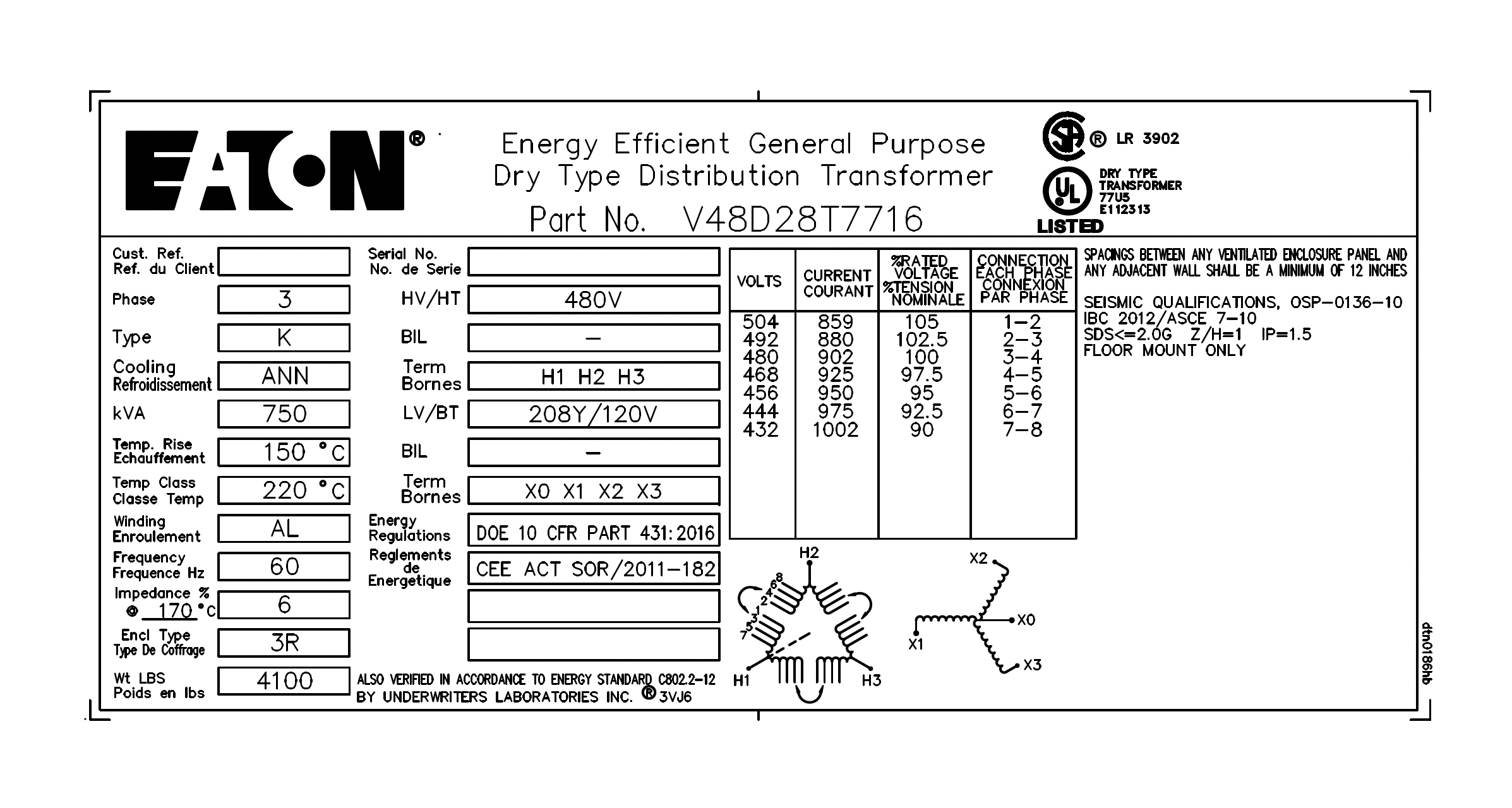
KVA Ratings:The nameplate kVA rating of a transformer represents the amount of kVA loading that will result in the rated temperature rise when the unit is operated under normal service conditions. When operating under these conditions (including the accepted hot-spot temperature with the correct class of insulation materials), you should achieve a "normal" life expectancy for the transformer.
Standard Voltage ratings for single Phase and three phase transformers:
FAQ: Can Transformers be Operated at Voltages other than Nameplate Voltages?In some cases, transformers can be operated at voltages below the nameplate rated voltage. In NO case should a transformer be operated at a voltage in excess of its nameplate rating unless taps are provided for this purpose. When operating below the rated voltage the KVA capacity is reduced correspondingly. For example, if a 480 volt primary transformer with a 240 volt secondary is operated at 240 volts, the secondary voltage is reduced to 120 volts and if the transformer were originally rated 10 KVA, the reduced rating Current Ratings:Single Phase Current\(I_{FLA}=\frac{KVA \cdot 1000}{V_{Phase}} \) Where:Phase voltage can be either Line-to-line or line-to-neutral Three Phase Current\(I_{FLA}=\frac{KVA \cdot 1000}{\sqrt{3}\cdot V_{Phase}} \) Frequency (Hz):
European power is typically 50Hz while North American power is usually 60hz.
Transformers cannot change the frequency of the source kva (voltage & current). If the source frequency is 60 Hz, the output will also be 60 Hz. In most parts of the Americas, it is typically 60Hz, and in the rest of the world it is typically 50Hz. Places that use the 50 Hz frequency tend to use 230 V RMS, and those that use 60Hz tend to use 117 V RMS. 
Winding Configurations
What is Meant by "Impedance" in Transformers?Impedance is the current limiting characteristic of a transformer and is expressed in percentage.
The percentage impedance of a transformer (Z%) is the
voltage drop on full load due to the winding resistance
and leakage reactance expressed as a percentage of the
rated voltage.
In general, impedance has a complex value, which means
that loads generally have a resistance to the source
that is in phase with a sinusoidal source signal and
reactance that is
out of phase with a sinusoidal source signal. Why is Impedance Important?It is used for determining the interrupting capacity of a circuit breaker or fuse employed to protect the primary of a transformer. Example: Determine a minimum circuit breaker trip rating and nterrupting capacity for a 10 KVA single phase transformer with 4% impedance, to be operated from a 480 volt 50 Hz source. Maximum Short Circuit Secondary CurrentThe maximum short circuit current that can be obtained from the output of the transformer is limited by the impedance of the transformer and is determined by multiplying the reciprocal of the impedance times the full load current. \(I_{FLA}=\frac{KVA \cdot 1000}{V_{phase} \cdot Z} \) Where: \( {V_{phase}: V_{Line-Line} } \) Z : %Z (decimal form) Example:Determine a minimum circuit breaker trip rating and interrupting capacity for a 10 KVA single phase transformer with 4% impedance, to be operated from a 480 volt 50 Hz source. Calculate as follows: Normal Full Load Current: \(= \frac{Nameplate Volt Amps}{Line Volts} \) \(= \frac{10,000 VA}{480V} \) Example:Determine a minimum circuit breaker trip rating and interrupting capacity for a 10 KVA single phase transformer with 4% impedance, to be operated from a 480 volt 50 Hz source. Calculate as follows: Maximum Short Circuit Amps: \(= \frac{Full Load Amps}{Z} \) \(= \frac{20.8 Amps}{0.04} =520 Amps\) Voltage Taps:Voltage supplied to a Transformer may vary from nominal voltage due to the distance from the substation or source. Higher or lower input voltage will result in higher or lower output voltage if there are no voltage adjustment taps present. In order to compensate for this voltage difference, transformers secondary voltage can be adjusted to nominal levels by adjusting the transformer's primary winding's voltage Tap. Transformer voltage taps change the voltage ratio of a transformer so that its secondary voltage stays at nominal. On large power transformers, taps on the primary are used to offset any higher or lower input voltages. These tap connections are usually set at the factory for nominal line voltage. If the voltage at the site is different, the taps are changed accordingly. Changing Voltage Taps
Standard tap arrangements are at two and one-half and five percent of the rated primary voltage for both high and low voltage conditions. For example, if the transformer has a 480 volt primary and the available line voltage is running at 504 volts, the pr'imary should be connected to the 5% tap above normal in order that the secondary voltage be maintained at the proper rating. The standard ASA and NEMA designation for taps are "ANFC" (above normal full capacity) and "BNFC" (below normal full capacity). 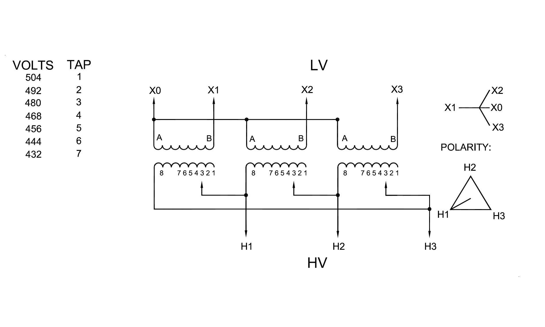
Temperature Rise:Transformer temperature rise is defined as the average temperature rise of the windings above the ambient (surrounding) temperature, when the transformer is loaded at its nameplate rating. Dry-type transformers are available in three standard temperature rises:
Liquid-filled transformers come in standard rises of 55C and 65C. These values are based on a maximum ambient temperature of 40C. That means, for example, that an 80C rise dry transformer will operate at an average winding temperature of 120C when at full-rated load, in a 40C ambient environment. (So-called hot spots within the transformer may be at a higher temperature than average.) Since most dry transformers use the same insulation on their windings (typically rated at 220C), irrespective of the design temperature rise, the 80C rise unit has more room for an occasional overload than a 150C rise unit, without damaging the insulation or affecting transformer life. Are Temperature Rise and Actual Surface Temperature Related?No. This can be compared with an ordinary light bulb. The filament temperature of a light bulb can exceed ■ 2000 degrees, yet the surface temperature of the bulb is low enough to perm-it touching with bare hands. Sound Level:Unless otherwise specified, transformer sound levels shall conform to ANSI/NEMA as follows:
K Factor:
Per the NEC, transformers feeding non-linear loads
shall be K-factor rated. What is BIL and How Does it Apply to Transformers ListedBIL is an abbreviation for Basic Impulse Level. Impulse tests are dielectric tests that consist of the application of a high frequency steep wave front voltage between windings, and between windings and ground. The Basic Impulse Level of a transformer is a method of expressing the voltage surge (lightning, switching surges, etc.) that a transformer will tolerate without breakdown. All transformers manufactured in this catalog, 600 volts and below, will withstand the NEMA standard BIL rating, which is 10 KV. This assures the user that he will not experience breakdowns when his system is properly protected with lightning arrestors or similar surge protection devices.
|
||||||||||||||||||||||||||||||||||||||||||||||||||||||||||||||||||||||||||||
| Transformer Test Procedures | |
|---|---|
| Dry Type, Low Voltage 600 volts or less |
|
| Transformer Test Procedure | |
|---|---|
| NETA Standard | |
NETA ATS7.2.1.1 Transformers, Dry Type, Air-Cooled, Low-Voltage, SmallNOTE: This category consists
of power transformers with windings
rated 600 volts or less and sizes
equal to or
|
|
| Transformer Turns Ratio | |
|---|---|
| DESCRIPTION: |
The transformer turns ratio test, or TTR test, confirms that the transformer has the correct ratio of primary turns to secondary turns |
| PURPOSE: |
Verifies the transformer's input and output voltage ratio. |
| PROCEDURE: |
Transformer Turns RatioSingle-Phase Models:Single-Phase Models:
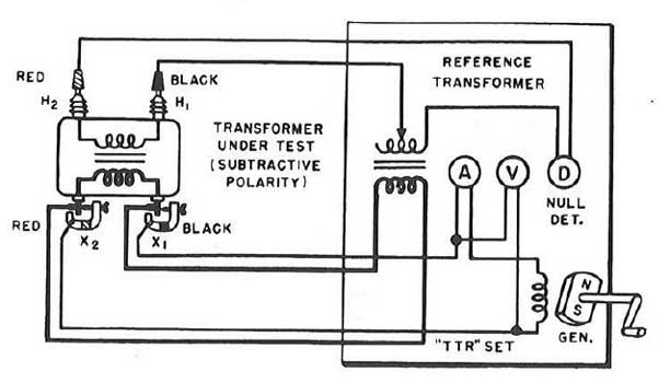
Transformer Turns Ratio
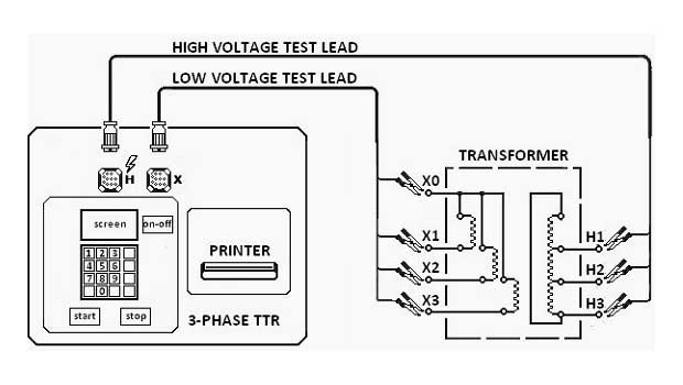
|
| Winding Resistance Test: | |
|---|---|
| PURPOSE: |
Winding resistance in transformers will change due to shorted turns, loose connections, or deteriorating contacts in tap changers. Regardless of the configuration, the resistance measurements are normally made phase-to-phase and the readings are compared with each other to determine if they are acceptable. |
| DESCRIPTION: |
This test measures the DC resistance of the transformer leads and windings and is made with a low-resistance ohmmeter or a Kelvin bridge. The test procedure for measuring DC winding resistance requires the transformer to be de-energized and isolated. Both the primary and secondary terminals should be isolated from external connections, and measurements made on each phase of all windings. The main purpose of this test is to check for gross differences between windings and for opens in the connections. Measuring the resistance of transformer windings assures that each circuit is wired properly and that all connections are tight. |
| PROCEDURE: |
Transformer winding resistance measurements are obtained by passing a known DC current through the winding under test and measuring the voltage drop across each terminal (Ohm's Law). Modern test equipment for this purposes utilizes a Kelvin bridge to achieve results; you might think of a winding resistance test set as a very large low-resistance ohmmeter (DLRO). |
| TEST RESULTS: |
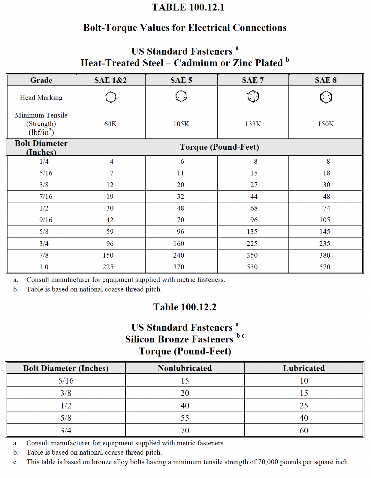
The IR test is of value for future comparative purposes and also for determining the suitability of the transformer of energizing or application of the high-potential (hi-pot) test. Insulation-resistance tests should be performed on winding-to-winding and each winding-to-ground. Apply voltage in accordance with manufacturer’s published data. In the absence of manufacturer’s published data, use Table 100.5. Calculate polarization index. |
| Test Equipment: |
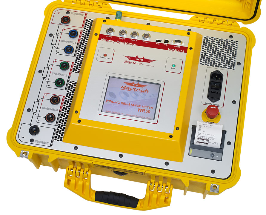
|
| Insulation Resistance | |
|---|---|
| PURPOSE: |
|
| DESCRIPTION: |
|
| PROCEDURE: |
Insulation Resistance Test:
Test Duration : 1 minute
Megohmmeter reading should be maintained for a period of 1 min. Test Connections
|
| TEST RESULTS: |
Polarization Index (PI) test:
Test Duration : 10 minute
A PI below 2 is indicative of insulation deterioration and
cause for further investigation.
This is an extension of the IR test. In this test, the two IR measurements are taken, the fi rst reading at 1 min and the second reading at 10 min. Then the ratio of the 10 min reading to 1 min reading is calculated to give the PI dielectric absorption value. A PI of winding-to-winding and winding-to-ground should be determined. NETA ATS TABLE
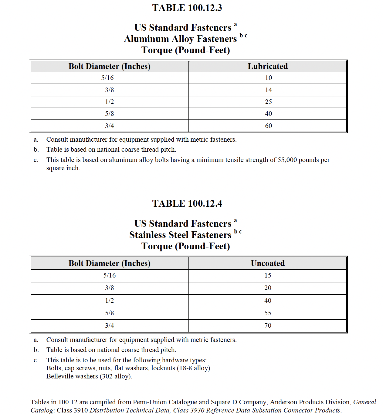
100.5
Electrical Apparatus and Systems Other han Rotating Machinery 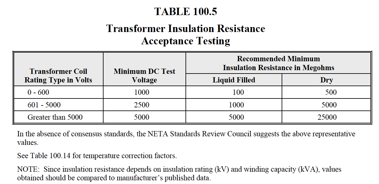
NETA MTS TABLE
100.5
Electrical Apparatus and Systems Other Than Rotating Machinery 
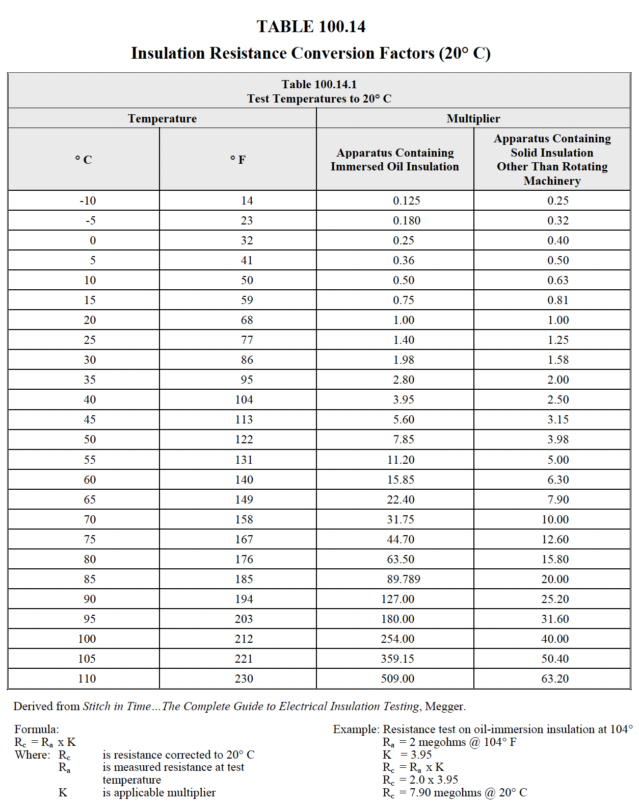
NETA ATS TABLE
100.14
|
| Circuit Breakers | |||||||||||||||||||||||||||||||||||||||||||||||||||||||||||||||||||||||||||||||||||||||||||||||||
|---|---|---|---|---|---|---|---|---|---|---|---|---|---|---|---|---|---|---|---|---|---|---|---|---|---|---|---|---|---|---|---|---|---|---|---|---|---|---|---|---|---|---|---|---|---|---|---|---|---|---|---|---|---|---|---|---|---|---|---|---|---|---|---|---|---|---|---|---|---|---|---|---|---|---|---|---|---|---|---|---|---|---|---|---|---|---|---|---|---|---|---|---|---|---|---|---|---|
| Transformer Protection | |||||||||||||||||||||||||||||||||||||||||||||||||||||||||||||||||||||||||||||||||||||||||||||||||

|
|||||||||||||||||||||||||||||||||||||||||||||||||||||||||||||||||||||||||||||||||||||||||||||||||
NEC Article 450: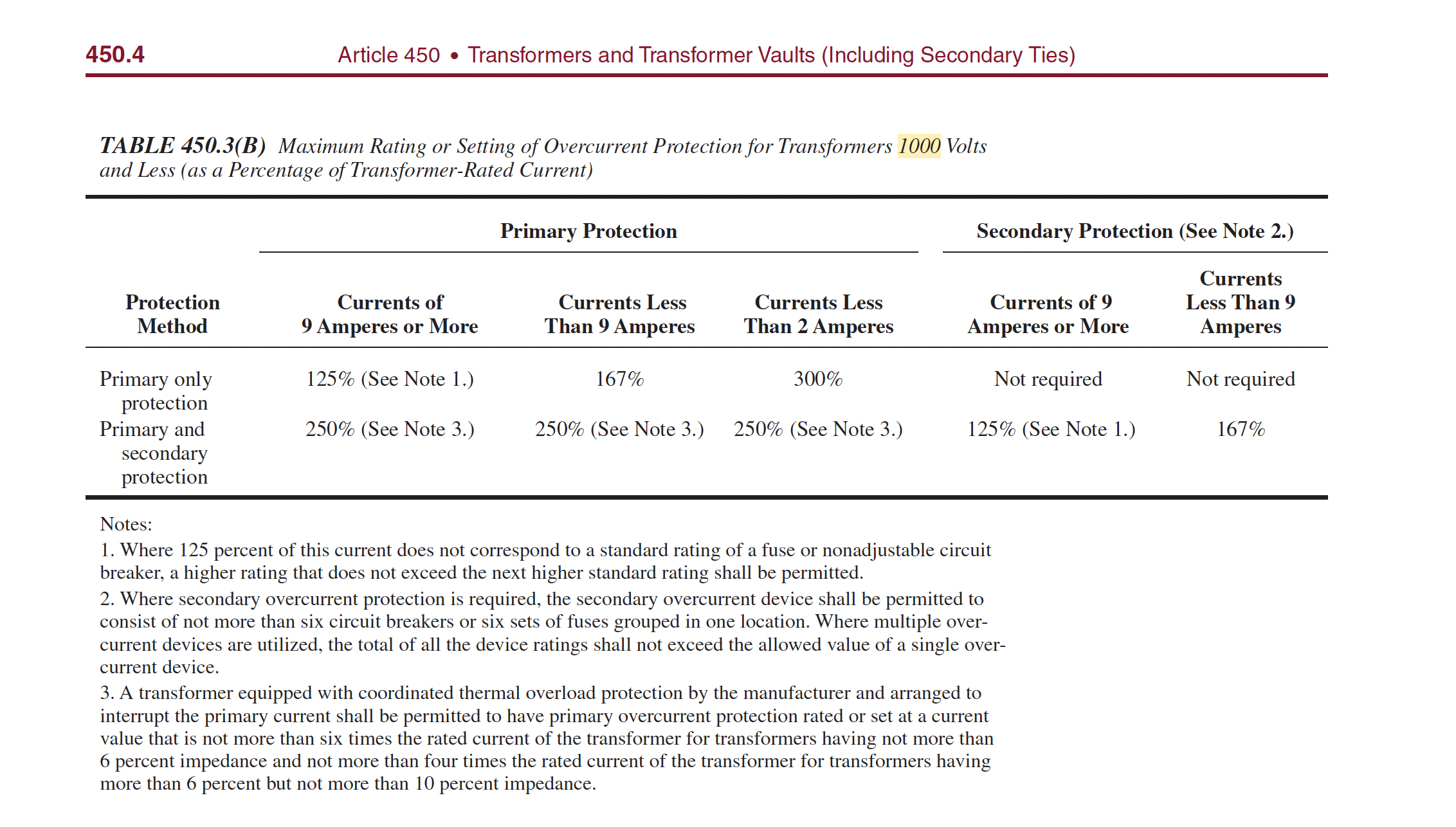
450.4 Autotransformers 1000 Volts, Nominal, or Less(A) Overcurrent Protection. Each autotransformer 1000 volts, nominal, or less shall be protected by an individual overcurrent device installed in series with each ungrounded input conductor. Such overcurrent device shall be rated or set at not more than 125 percent of the rated full-load input current of the autotransformer. Where this calculation does not correspond to a standard
Primary and Secondary Protection Chart
Standard Voltage ratings for single Phase and three phase transformers:
FAQ: Can Transformers be Operated at Voltages other than Nameplate Voltages?In some cases, transformers can be operated at voltages below the nameplate rated voltage. In NO case should a transformer be operated at a voltage in excess of its nameplate rating unless taps are provided for this purpose. When operating below the rated voltage the KVA capacity is reduced correspondingly. For example, if a 480 volt primary transformer with a 240 volt secondary is operated at 240 volts, the secondary voltage is reduced to 120 volts and if the transformer were originally rated 10 KVA, the reduced rating Current Ratings:\(I_{FLA}=\frac{KVA \cdot 1000}{V_{Phase}} \) \(I_{FLA}=\frac{KVA \cdot 1000}{\sqrt{3}\cdot V_{Phase}} \) Where:
Frequency (Hz):
European power is typically 50Hz while North
American power is usually 60hz.
Transformers cannot change the frequency of the source kva (voltage & current). If the source frequency is 60 Hz, the output will also be 60 Hz. In most parts of the Americas, it is typically 60Hz, and in the rest of the world it is typically 50Hz. Places that use the 50 Hz frequency tend to use 230 V RMS, and those that use 60Hz tend to use 117 V RMS. Winding Configurations
What is Meant by "Impedance" in Transformers?Impedance is the current limiting characteristic of a transformer and is expressed in percentage.
The percentage impedance of a transformer (Z%) is the
voltage drop on full load due to the winding resistance and
leakage reactance expressed as a percentage of the rated
voltage.
In general, impedance has a complex value, which means that
loads generally have a resistance to the source that is in
phase with a sinusoidal source signal and reactance that is
out of phase with a sinusoidal source signal. Why is Impedance Important?It is used for determining the interrupting capacity of a circuit breaker or fuse employed to protect the primary of a transformer. Example: Determine a minimum circuit breaker trip rating and nterrupting capacity for a 10 KVA single phase transformer with 4% impedance, to be operated from a 480 volt 50 Hz source. Maximum Short Circuit Secondary CurrentThe maximum short circuit current that can be obtained from the output of the transformer is limited by the impedance of the transformer and is determined by multiplying the reciprocal of the impedance times the full load current. \(I_{FLA}=\frac{KVA \cdot 1000}{V_{phase} \cdot Z} \) Where: \( {V_{phase}: V_{Line-Line} } \) Z : %Z (decimal form) Example:Determine a minimum circuit breaker trip rating and interrupting capacity for a 10 KVA single phase transformer with 4% impedance, to be operated from a 480 volt 50 Hz source. Calculate as follows: Normal Full Load Current: \(= \frac{Nameplate Volt Amps}{Line Volts} \) \(= \frac{10,000 VA}{480V} \) Example:Determine a minimum circuit breaker trip rating and interrupting capacity for a 10 KVA single phase transformer with 4% impedance, to be operated from a 480 volt 50 Hz source. Calculate as follows: Maximum Short Circuit Amps: \(= \frac{Full Load Amps}{Z} \) \(= \frac{20.8 Amps}{0.04} =520 Amps\) Voltage Taps:Voltage supplied to a Transformer may vary from nominal voltage due to the distance from the substation or source. Higher or lower input voltage will result in higher or lower output voltage if there are no voltage adjustment taps present. In order to compensate for this voltage difference, transformers secondary voltage can be adjusted to nominal levels by adjusting the transformer's primary winding's voltage Tap. Transformer voltage taps change the voltage ratio of a transformer so that its secondary voltage stays at nominal. On large power transformers, taps on the primary are used to offset any higher or lower input voltages. These tap connections are usually set at the factory for nominal line voltage. If the voltage at the site is different, the taps are changed accordingly. 
|
|||||||||||||||||||||||||||||||||||||||||||||||||||||||||||||||||||||||||||||||||||||||||||||||||


