


| Arc Flash Hazard Analysis Report | ||
|---|---|---|
| Arc Flash Hazard Analysis Report |
An Arc Flash Assessment / Analysis is a study of a facility’s power system. Its purpose is to determine the available incident energy values at specific locations where personnel would "interact" or be exposed to live or energized electrical equipment. |
|
| Incident Energy Report | |
|---|---|
|
|
BLAH BLAH BLAH BLAH BLAH BLAH
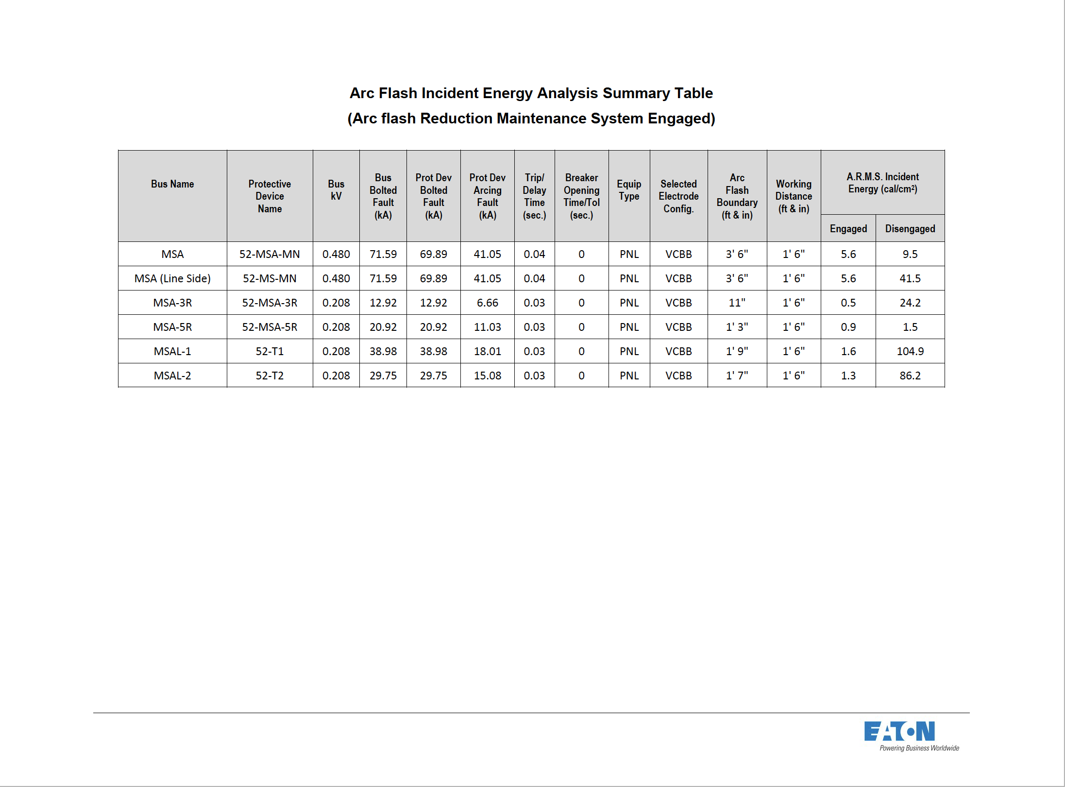
The names in this column correlate to the names implemented in the software system model. These locations correspond to plant locations such as main switchboards, panelboards, enclosed breakers, etc. The values in this column show the nominal voltage of the bus location noted under Bus Name heading. This column lists the name of the device primarily responsible for clearing a potential fault at the associated bus. Again, these device names correlate to the system model.
This column shows the bolted fault current available for the bus location referenced. This current value corresponds to the system operating conditions that will result in the worst- case calculated value for thermal energy. This column displays the portion of calculated bolted fault currents (Bus Bolted Fault column) that is contributed through the protective device referenced in Column #2.
This column displays the portion of calculated arcing fault currents that is contributed through the protective device referenced under protective device Name column. These values demonstrate a reduction in available fault current due to the arc resistance.
This column displays the portion of calculated arcing fault currents that is contributed through the protective device referenced under protective device Name column. These values demonstrate a reduction in available fault current due to the arc resistance.
This column displays the portion of calculated arcing fault currents that is contributed through the protective device referenced under protective device Name column. These values demonstrate a reduction in available fault current due to the arc resistance.
This column displays the portion of calculated arcing fault currents that is contributed through the protective device referenced under protective device Name column. These values demonstrate a reduction in available fault current due to the arc resistance. VCB:Vertical electrodes terminating in an insulating barrier inside an enclosure. 
VCBB:Vertical electrodes terminating in an insulating barrier inside an enclosure. 
HCB:Horizontal electrodes inside an enclosure. 
VOAElectrodes in Open Air. Vertical electrodes in open air. 
HOAElectrodes in Open Air. Horizontal electrodes in open air. 
BLAh, BLAh , BLAh , BLAh
BLAh, BLAh , BLAh , BLAh
BLAh, BLAh , BLAh , BLAh |
|