SIDEBAR SKINS

HEADER SKINS

Total Collections
Arc Flash Analysis
Terminology
Electric Arc:

An electric arc or an arcing fault is the flow of electric current through the air from one conductor to another or to ground. Arcs are generally initiated by a flashover caused by some type of conductor that subsequently vaporizes or falls away, leaving an arc. Arcing faults create many hazards, but the greatest risk is burn injuries due to exposure to the heat generated by the arc. This heat can cause serious, even fatal burns, as well as ignite clothing and other nearby material and objects. In addition, electric arcs can produce molten metal droplets, UV radiation, and explosive air pressure waves.

Arc Flash Hazard:

An arc flash hazard is a dangerous condition associated with the possible release of energy caused by an electric arc. An arc flash hazard may exist when energized electrical conductors or circuit parts are exposed or when they are within equipment in a guarded or enclosed condition, provided a person is interacting in a way that can cause an arc (such as switching on or off a breaker or disconnect switch; racking a breaker…things of this nature). Also, under normal operating conditions, enclosed energized electrical equipment that has been properly i nstalled and maintained is not likely to pose an arc flash hazard.

Arc Flash Hazard Analysis Report:

An Arc Flash Assessment / Analysis is a study of the facility’s power system to determine the incident energy available at specific electrical devices that employees would be exposed to while “interacting with” the electrical equipment at the facility. The output of the Assessment/ Analysis is a determination and labeling of the PPE required of the electrical devices, suitability of the devices for service as installed and if there are any miss- coordination issues involved as the system is currently installed.

A short circuit current available analysis and the clearing times of the overcurrent devices involved is required to determine the incident energy at the various points in the system.

Power Transformer Nameplate Data
MV Transformer Nameplate
General Information
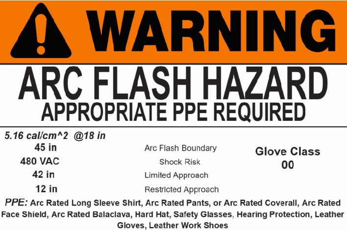
  1. Arc Flash labels should meet the requirements found in NFPA 70E and CSA Z462
  2. Long Sleeve Shirt (or Jacket) and Pants or AR Coverall with minimum arc rating of 4 cal/cm2
  3. Required Face and Head Protection: Face Shield (with “wrap around” guarding…i.e balaclava) or Arc Flash Suit Hood
Incident Energy

Incident energy is the amount of thermal energy impressed on a surface, a certain distance from the source, generated during an electric arc event. It is based on the available fault current, working distance, and the clearing time of the fault. The unit of measurement for incident energy is calories per centimeter squared. To give you an idea of what this means, 1 cal/cm2 is equivalent to the energy produced from a lighter in one second.

Arc Flash Boundary

Arc Flash Boundary is the distance from the arc at which a person could receive a second degree burn, which begins at 1.2 cal/cm2. Just as a note, a third degree burn begins at 10.7 cal/cm2.

This is the shortest distance at which a person working at the time of an arc-flash may receive permanent injury (the onset of a second degree burn or worse) if not properly protected by flame-resistant (FR) clothing.

Shock Boundary

Most electrical equipment that poses an arc flash hazard also presents a shock hazard, so many arc flash labels also include these boundaries to protect workers from this second concern. The Limited Approach Boundary is a distance from the equipment that should only be crossed by “qualified” (properly trained and equipped) workers, or other workers when they are properly equipped and accompanied by a qualified worker. The Restricted Approach Boundary, which is closer to the equipment, should only be crossed by qualified workers, and only when they have a written and approved plan of action.

Limited Approach

Moving toward the energized and exposed equipment, you’ll find the limited approach boundary. Within this boundary, it is still possible to be exposed to a shock hazard. Appropriate PPE should be worn by qualified workers in the limited space (space between the limited approach boundary and the restricted boundary).Non-qualified workers should stay outside of this boundary unless wearing proper PPE and being escorted by a worker with specialized training.

These boundaries are defined in more detail in our Arc Flash Workplace Safety Guide. The “prohibited approach” boundary was removed in the 2015 NFPA 70E edition.

Restricted Approach
Glove Categories
Insulated Rubber Gloves
  1. TYPE I- Designates Natural Rubber
  2. TYPE I- SALCOR® UV and Ozone Resistant Rubber
ASTM Labeling Chart
Natural Rubber Electrical Insulation Gloves
Class Color Proof Test
Voltage AC/DC
Max Use
Voltage AC/DC
Max Use
Insulated Rubber
Glove Label
00 Beige 2,500/10,000 500/750
0 Red 5,000/20,000 1,000/1,500
1 White 10,000/40,000 7,500/11,2500
2 Yellow 20,000/45,000 17,000/25,500
3 Green 30,000/60,000 26,500/39,750
3 Orange 40,000/70,000 36,000/54,000
CAT
No.
Minimum
Arc Rating
Description
1 4-8 cal/cm 2

PPE CAT 1 represents the lowest level in which Arc Rated PPE is required. Requiring a single layer of arc-rated PPE, workers need the following clothing:

    Required Clothing:
  1. Long Sleeve Shirt (or Jacket) and Pants or AR Coverall with minimum arc rating of 4 cal/cm2
  2. Required Face and Head Protection: Face Shield (with “wrap around” guarding…i.e balaclava) or Arc Flash Suit Hood
  3. As Needed: Arc Rated Jacket, Rainwear, Parka, Hard Hat Liner
  4. In addition to AR clothing, the following products are required or to be used as needed:
  5. In addition to AR clothing, the following products are required or to be used as needed:
  6. Required Hand Protection: Heavy-Duty Leather Gloves Additional PPE: Hard Hat, Eye Protection (Glasses, Goggles), Hearing Protection Footwear: Leather Footwear (as needed))
2 8-25 cal/cm2

PPE CAT 2 can likely be met with a single layer of Arc Rated PPE. In fact, the majority of companies with exposures requiring CAT 1 typically opt for CAT 2 clothing to cover both categories. Today, the comfort of PPE CAT 1 and 2 is comparable so it makes more sense to choose CAT 2 clothing.

In PPE CAT 2, workers need the following clothing:
  1. Required Clothing: Arc Rated Long Sleeve Shirt and Pants or Arc Rated Coverall with minimum arc rating of 8 cal/cm2
  2. Required AR Face and Head Protection: Arc Rated Arc Flash Suit Hood or AR Face Shield, Sock Hood/Balaclava with minimum arc rating of 8 cal/cm2
  3. As Needed: Arc Rated Jacket, Rainwear, Parka, Hard Hat Liner
  4. In addition to AR clothing, the following products are required or to be used as needed:
  5. In addition to AR clothing, the following PPE is required:
  6. Required Hand Protection: Heavy-Duty Leather Gloves Additional PPE: Hard Hat, Eye Protection (Glasses, Goggles), Hearing Protection Footwear: Leather Footwear (as needed)
3 25 - 40 cal/cm2

PPE Category 3 and 4 require additional layers of PPE. Arc flash suit hoods are required and rubber insulating gloves & leather protectors or arc rated gloves are required. For PPE Category 3; workers need the following clothing:

Required Clothing:
  1. Arc Rated Flash Suit Jacket and AR pnt or AR coverall with minimum arc rating of 25 cal/cm2
  2. Required AR Face and Head Protection: Arc Rated Flash Suit Hood with minimum arc rating of 25 cal/cm2
  3. Required AR Hand Protection: Rubber insulating gloves & leather protectors or arc rated gloves
  4. Required AR Hand Protection: Rubber insulating gloves & leather protectors or arc rated gloves
  5. In addition to AR clothing, the following PPE is required:
  6. Additional PPE: Hard Hat, Eye Protection (Glasses, Goggles), Hearing Protection (inserts), Leather Footwear
4 40
cal/cm2
  1. Required Clothing: Arc Rated Flash Suit Jacket and AR pant or AR coverall with minimum arc rating of 40 cal/cm2
  2. Sequired AR Face and Head Protection: Arc Rated Flash Suit Hood with minimum arc rating of 40 cal/cm2
  3. Required AR Hand Protection: Rubber insulating gloves & leather protectors or arc rated gloves
  4. As Needed: Arc Rated Jacket, Rainwear, Parka, Hard Hat Liner
IEEE 1584-2002 Method
Calculating Arc Flash Energy

There are two distinct mathematical methods of calculating the available arc flash energy present at a specific piece of equipment — both of which are detailed in Annex D of NFPA 70E.

Arc Flash Calculation Engineering Analysis Methods

IEEE 1584-2002 is titled “IEEE Guide for Performing Arc-Flash Hazard Calculations,” and provides a methodology for calculating prospective arc flash hazards. Based on test data, the IEEE 1584 committee developed empirical equations to calculate arc flash incident energy for AC systems. It is important to understand that the IEEE 1584 equations are valid only for the conditions for which test data was evaluated.These limitations are summarized in the table below summarized in Table 3.1

Applicable Conditions for Use of the IEEE 1584 Calculation Method
System voltage (kV): 0.208 to 15 kV
Frequencies (Hz): 50 or 60 Hz
Bolted fault current (kA): 0.7 to 106 kA
Gap between electrodes (mm): 13 to 152 mm/
Equipment enclosure type: Open air, box, MCC, panel, switchgear, cables
Grounding type: Ungrounded, grounded, high resistance grounded
Types of faults: 3 phase faults ONLY
  1. Low Voltage Systems
  2. Less than 1000V
  3. The Arc Current is Given by Equation:

\(I_{a} = 10^{\color{green} {K}+ 0.662\log_{10}({I_{bf} }) +0.0966\color{red} {V} +0.000526\cdot \color{blue} {G}+ 0.5588\cdot \color{red} {V}\cdot \log_{10}({I_{bf} })-0.00304 \cdot \color{blue} {G} \cdot \log_{10}({I_{bf} }) }\)

  1. Where:
  2. \(I_{a}=\) \(\text{Arcing Current (kA)}\)
  3. \(\color{green} {K} = -0.153\) \(\text{; Open configuration}\)
  4. \(\color{green} {K} = -0.153\) \(\text{; Box configuration}\)
  5. \(I_{bf}=\) \(\text{Bolted Fault Current for 3-Phase Faults (symmetrical RMS) }\)
  6. \(\color{red} {V}=\) \(\text{System Voltage (kV) }\)
  7. \(\color{blue} {G}=\) \(\text{Gap Between Conductors }\)
  1. Medium Voltage Systems
  2. Greater than 1000V
  3. The Arc Current is Given by Equation:

\(I_{a} = 10^{0.00402 + 0.983\log_{10}({I_{bf}})}\)

  1. Where:
  2. \(I_{a}=\) \(\text{Arcing Current (kA)}\)
  3. \(I_{bf}=\) \(\text{Bolted Fault Furrent for 3-Phase Faults (symmetrical RMS) }\)

Estimate of Normalized Incident Energy

  1. The Normalized Incident Energy Equation is based on :
  2. 2 second Arc Duration
  3. 610 mm Distance from the Arc
\(E_{n}=\) \( \text{incident energy normalized for time and distance } ( J/cm^{2}) \)

\(E_{n} = 10^{ \color{green} {K_{1}} + \color{green} {K_{2}} + 1.081\cdot \log_{10}({I_{a} }) + 0.0011\cdot \color{blue} {G}} \)

  1. Where:
  2. \(\color{green} {K_{1}} = 0.792\) \(\text{; Open Configuration}\)
  3. \(\color{green} {K_{1}} = -0.555\) \(\text{; Box Configuration}\)
  4. \(\color{green} {K_{2}} = 0\) \(\text{; Ungrounded and High Resistance Grounded Systems}\)
  5. \(\color{green} {K_{2}} = -0.113\) \(\text{; Grounded Systems}\)
  6. \(\color{blue} {G}=\) \(\text{ Gap Between Conductors (mm) }\)

Estimate of Incident Energy

The normalized incident energy is used to obtain the estimated incident energy at a normal surface at a given distance and arcing time with equation

\(E=\) \( \text{Incident Energy } ( J/cm^{2}) \)

\(E = 4.184\cdot \color{blue} {C_{f}}\cdot \color{green} {E_{n}}\cdot \left(\begin{array}{c}\frac{t}{0.2} \end{array}\right) \cdot \left(\begin{array}{c} \frac{610}{D} \end{array}\right)^{x} \)

  1. Where:
  2. \( \color{green} {E_{n}}\) \( \text{Normalized Incident Energy } ( J/cm^{2}) \)
  3. \(\color{blue} {C_{f}}= \) \(\text{Calculation Factor = 1.0 ; Voltage > 1kV } \)
  4. \(\color{blue} {C_{f}}= \) \(\text{Calculation Factor = 1.5 ; Voltage < 1kV } \)
  5. \( t : \) \(\text{Arcing Time (seconds)}\)
  6. \( D : \) \(\text{Working Distance from Arc (mm)}\)
  7. \( x : \) \(\text{ Distance Exponent }\)

Arc Flash-Protection Boundary

The distance at which a person without personal protective equipment (PPE) may get a second degree burn that is curable. This is the same as the Arc Flash Boundary discussed in NFPA 70E.

\(\large D_{B}=\) \(\text{Distance of the Boundary from the Arcing Point (mm)} \)

\( D_{B} = 610 \cdot \begin{bmatrix} 4.184 \cdot \color{blue} {C_{f}} \cdot \color{green} {E_{n}}\cdot \left(\begin{array}{c}\frac{t}{0.2} \end{array}\right) \left(\begin{array}{c}\frac{1}{E_{b}} \end{array}\right) \end{bmatrix}^{\frac{1}{x}} \)

  1. Where:
  2. \(\color{blue} {C_{f}}= \) \(\text{Calculation Factor = 1.0 ; Voltage > 1kV } \)
  3. \(\color{blue} {C_{f}}= \) \(\text{Calculation Factor = 1.5 ; Voltage < 1kV } \)
  4. \(E_{n}=\) \( \text{incident energy normalized } ( J/cm^{2}) \)
  5. \( t : \) \(\text{Arcing Time (seconds)}\)
  6. \( x : \) \(\text{ Distance Exponent }\)
  7. \(E_{B}=\) \( \text{incident energy at the boundary distance } ( J/cm^{2}) \);
  8. \(E_{B}\) \(\text{ can be set at 5.0 } J/cm^{2} (1.2 Cal/cm^{2}) \) \( \text{for bare skin } \)